Optical tracking sensor method

a tracking sensor and optical tracking technology, applied in static indicating devices, instruments, material analysis, etc., can solve the problems of no known prior art having the ability to induce motion-induced remote wake-up

Inactive Publication Date: 2006-06-06
ON SEMICONDUCTOR TRADING LTD +2
View PDF9 Cites 17 Cited by
  • Summary
  • Abstract
  • Description
  • Claims
  • Application Information

AI Technical Summary

Benefits of technology

[0015]An advantage of the present invention is that it has multiple means of compensating for non-uniform illumination.
[0016]Another advantage of the present invention is that it has multiple means of checking the output results.

Problems solved by technology

Occasionally, due to noise and non-uniformities, the block matching algorithm finds a false match.
If the difference between the best block match comparison matrix and the worst block match comparison matrix is too small, then the work surface is likely to be too smooth and too devoid of features for proper operation.
No known prior art has motion induced remote wake-up capability.
Every time this replacement is made, there is a certain amount of quantization error that accumulates as a real displacement value is rounded off to an integer value.

Method used


Image

  • Optical tracking sensor method
  • Optical tracking sensor method
  • Optical tracking sensor method

Examples


Embodiment Construction

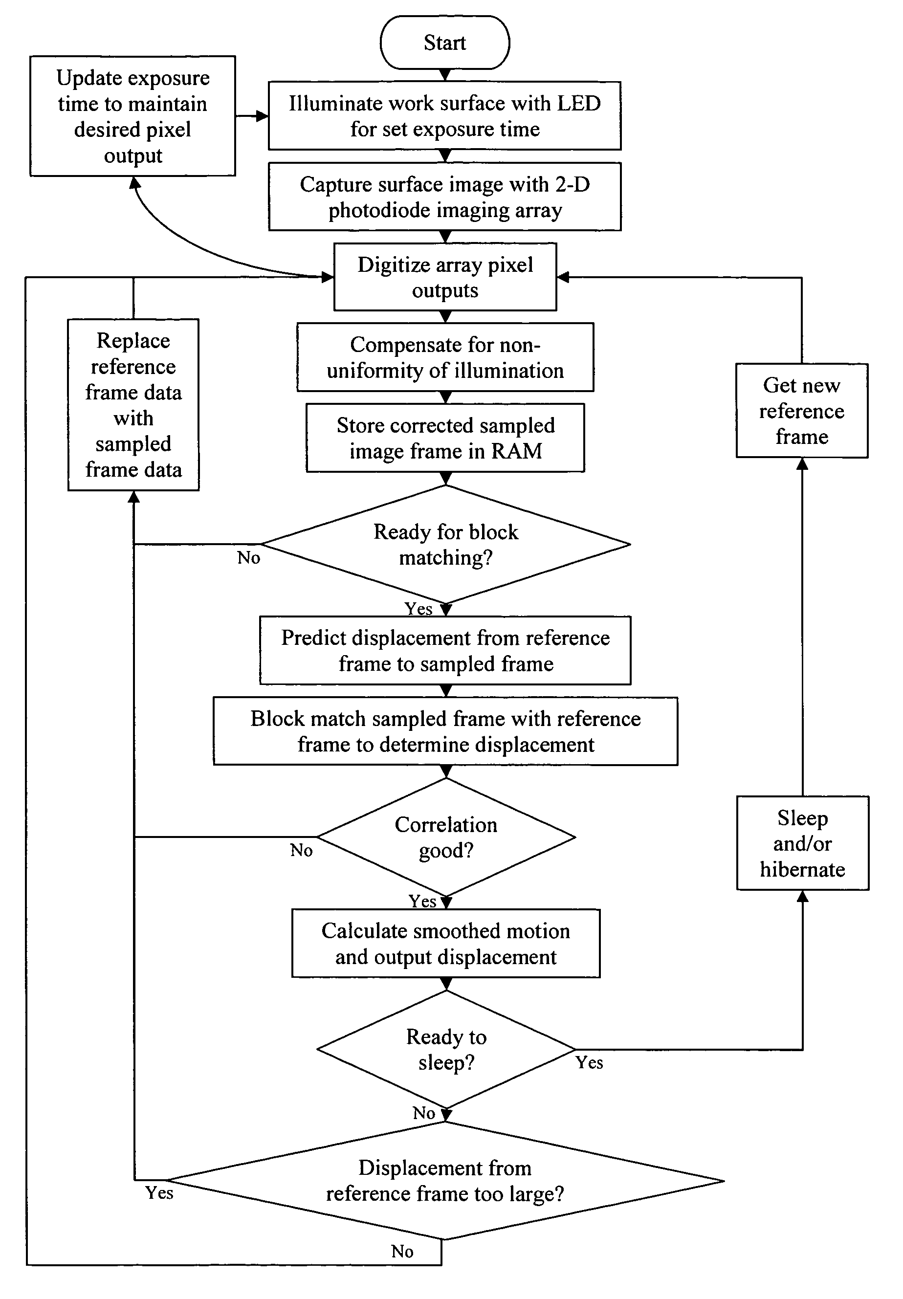
[0024]The present invention is a method of using an optical sensor to determine displacement relative to a work surface. FIG. 3 shows the functional block structure of the invention, and FIG. 4 demonstrates a typical floor plan of an integrated circuit implementation of the method. The imaging sensor used in the system is a two-dimensional array of photodiodes that is positioned at the focused image of the work surface. The incidence of photons on the silicon in the image sensor array pixels generates electrons that are collected by the pixel photodiodes. After a collection (or integration) period, a frame of pixel signals is read out and converted to digital values by the ADC (analog / digital converter). The digital image data is passed through a filter and / or correction circuitry. The filtered data from an image frame is then stored in one of two or three memory banks.

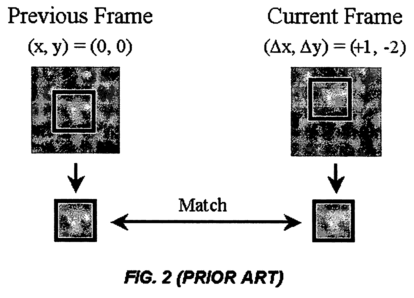
[0025]As the mouse (or other device containing the sensor) is moved, another image is captured and stored in the sa...


PUM

PropertyMeasurementUnit
displacement vectorsaaaaaaaaaa
vertical displacementaaaaaaaaaa
displacementaaaaaaaaaa

Abstract

The present invention is a method of optical tracking sensing using block matching to determine relative motion. The method includes three distinct means of compensating for non-uniform illumination: (1) a one-time calibration technique, (2) a real-time adaptive calibration technique, and (3) several alternative filtering methods. The system also includes a means of generating a prediction of the displacement of the sampled frame as compared to the reference frame. Finally, the method includes three cumulative checks to ensure that the correlation of the measured displacement vectors is good: (1) ensuring that “runner-up” matches are near the best match, (2) confirming that the predicted displacement is close to the measured displacement, and (3) block matching with a second reference frame.

Description

BACKGROUND OF THE INVENTION[0001]1. Field of the Invention[0002]The present invention relates generally to scanning devices, and more particularly is an optical tracking sensor method such as may be used in a computer mouse.[0003]2. Description of the Prior Art[0004]An optical sensor that can detect relative motion and position is very useful as a component of an optical computer mouse, and in other very useful optical tracking applications. The purpose of the optical sensor is to detect relative motion between the sensor and a patterned or textured “work” surface. The optical sensor works by capturing successive images of a patterned and / or textured work surface, and then determining successive displacement vectors.[0005]FIG. 1 shows the basic components of a current art optical mouse system. A light source and an optical waveguide illuminate a pattern in a work surface. The pattern is often microscopic and not readily visible to the naked eye. An optical lens images the work surfa...

Claims


Application Information

Patent Timeline
Patent Type & Authority Patents(United States)
IPC IPC(8): H01L27/00G01N21/86G06K7/015G09G5/08
CPCG06F3/0317
Inventor WANG, CHINLEE
Owner ON SEMICONDUCTOR TRADING LTD
Why Eureka
Try Eureka