Radiation detecting cassette

Active Publication Date: 2006-06-06
FUJIFILM HLDG CORP +1
View PDF11 Cites 16 Cited by
  • Summary
  • Abstract
  • Description
  • Claims
  • Application Information

AI Technical Summary

Benefits of technology

[0009]The present invention was accomplished in view of the foregoing problems, and has an object to provide a radiation detecting cassette which impro

Problems solved by technology

Therefore, if the solid-state radiation detector is subjected to a shock in the direction towards the bottom thereof, shock cannot be absorbed.
On the other hand, when elastomeric bodies such as rubber or gel are used to sandwich the solid-state radiation detector therebetw

Method used


Image

  • Radiation detecting cassette
  • Radiation detecting cassette
  • Radiation detecting cassette

Examples


Embodiment Construction

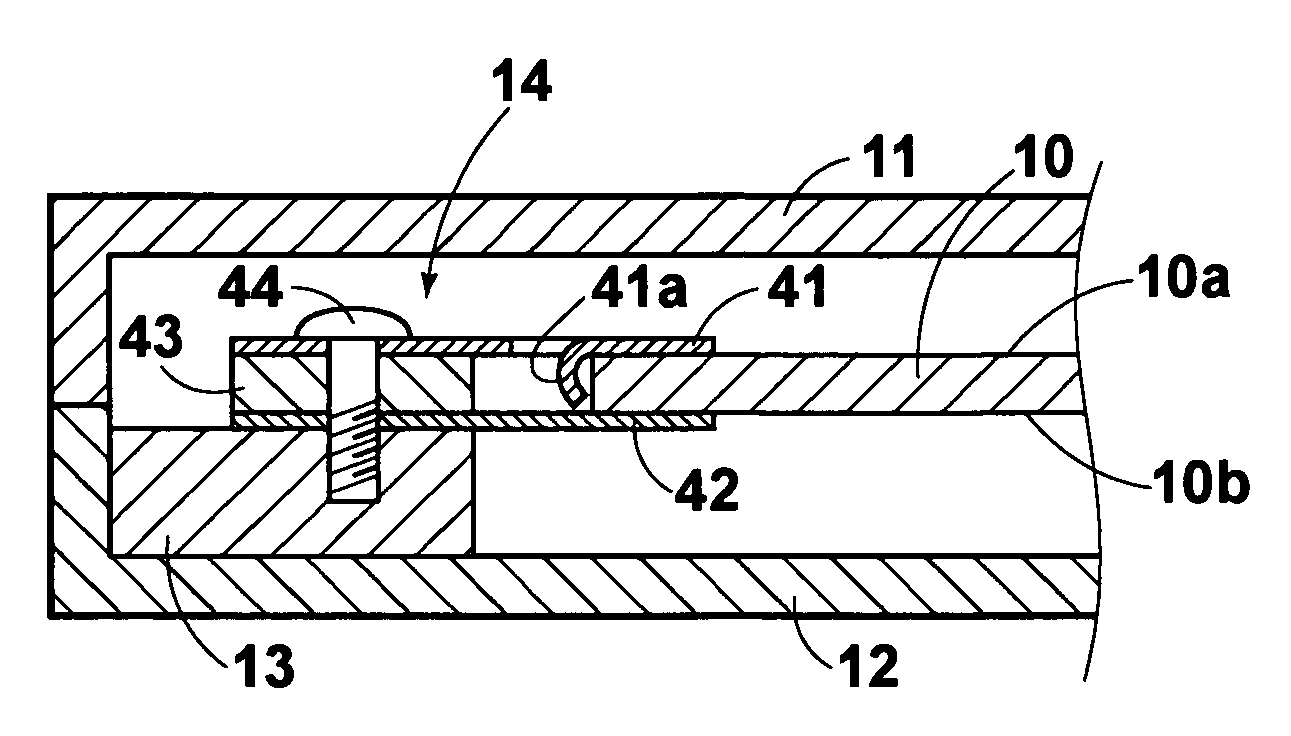
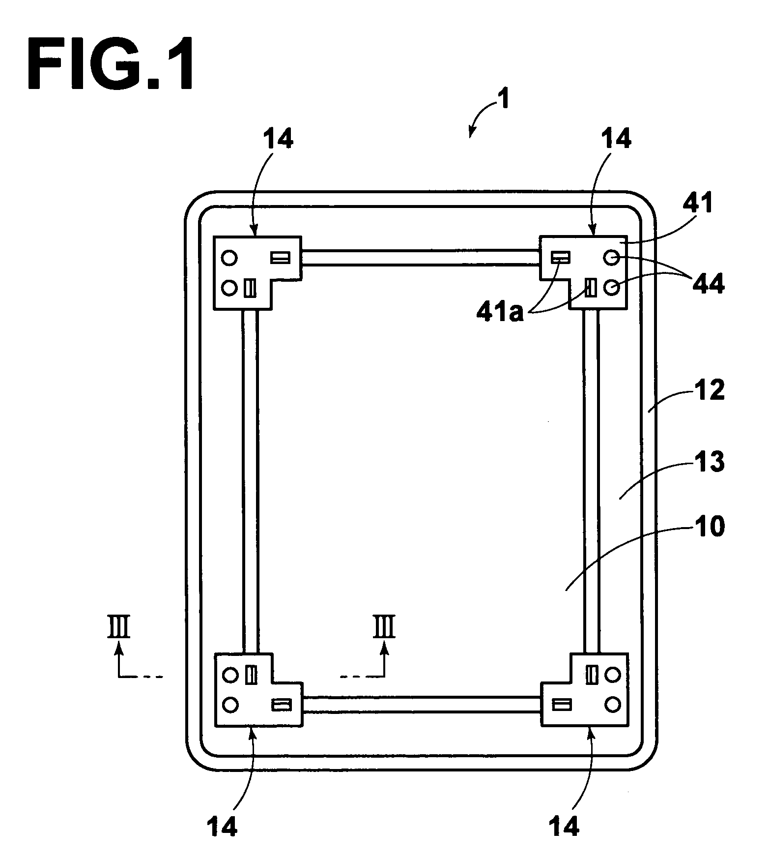
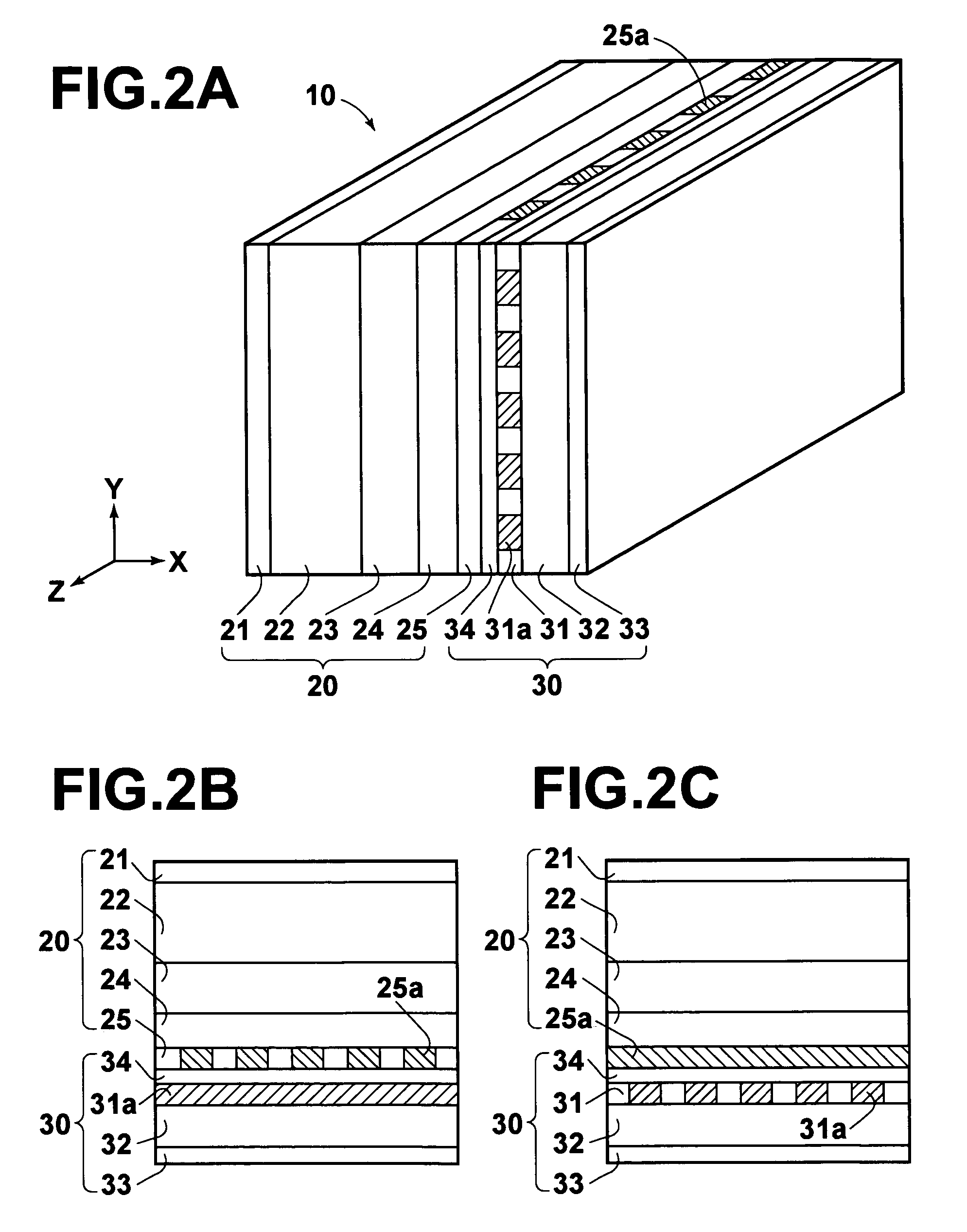
[0020]The present invention will now be explained in connection with embodiments thereof with reference to the accompanying drawings. FIG. 1 is a plan view of an embodiment of a radiation detecting cassette according to the invention, with an upper shell half removed, FIG. 2A is a perspective view of a solid-state radiation detector used for the radiation detecting cassette in FIG. 1, and FIG. 2B is a cross sectional view taken through plane X-Y of FIG. 2A, FIG. 2C is a cross sectional view taken through plane X-Z of FIG. 2A, and FIG. 3 is a cross sectional view of the radiation detecting cassette including the upper shell half, taken along line III—III of FIG. 1.

[0021]A radiation detecting cassette 1 comprises a casing constituted by upper and lower shell halves 11, 12, and a frame 13 fixed in the shell halves. The radiation detecting cassette 1 includes a solid-state radiation detector 10 which is an image pickup device, an electric circuit board (not shown) for providing an image...


PUM


Abstract

A radiation detecting cassette 1 includes a casing constituted by upper and lower shell halves 11, 12 and a frame 13 fixed therein; and a solid-state radiation detector 10 which is an image pickup device. Four corners of the solid-state radiation detector 10 are sandwiched by plate springs 41 and 42 both of which are fixed to the frame 13.

Description

BACKGROUND OF THE INVENTION[0001]1. Field of the Invention[0002]This invention relates to a radiation detecting cassette having a radiation detector accommodated within a casing.[0003]2. Description of the Related Art[0004]In the field of radiography for medical diagnosis and the like, various solid-state radiation detectors (whose main part comprises semiconductors; hereinafter also simply referred to as “detectors”) which detect radiation penetrating an object and produce an image signal carrying radiographic image information of the object have recently been proposed and brought into actual use (see, for example, U.S. Pat. No. 6,268,614 hereinafter referred to as Patent Reference 1 and Japanese Unexamined Patent Publication No. 2000-284056 hereinafter referred to as Patent Reference 2). Various radiation detecting cassettes having a case accommodating therein such a solid-state radiation detector and the like have also been proposed (see, for example, U.S. Patent Laid-Open No. 20...

Claims


Application Information

Patent Timeline
IPC IPC(8): G01T1/20G01T1/24H01L25/00H01L27/00H01L27/146H05G1/64G01T1/00G01T1/29G01T7/00G03B42/02H01L31/09
CPCG01T1/2928
Inventor YAGI, KEIICHI
Owner FUJIFILM HLDG CORP
Why Eureka
Try Eureka