Mechanical drive system operating by magnetic force

a magnetic drive and magnetic force technology, applied in the direction of positive displacement liquid engine, magnetic circuit rotating parts, magnetic circuit shape/form/construction, etc., can solve the problem of magnet being drawn against the sleeve, it is practically impossible to detach a magnet in order to reposition, and it is difficult to achieve a high degree of accuracy in the positioning of the magnet on the sleev

Inactive Publication Date: 2006-06-06
C D R POMPE
View PDF14 Cites 59 Cited by
  • Summary
  • Abstract
  • Description
  • Claims
  • Application Information

AI Technical Summary

Benefits of technology

[0019]This problem is solved by means of a mechanical drive system operating by magnetic force of the type specified above, characterized in that at least one of the driving element and the driven element of the drive system comprises a cage provided with seats for housing the respective driving magnets or driven magnets.
[0020]The problem is also solved by means of a magnet for a mec...

Problems solved by technology

Since the operator loses control of the magnet during the last portion of its movement, it is difficult to achieve a high degree of accuracy in the positioning of the magnets on the sleeve and, in the event of incorrect positioning, it is practically impossible to detach a magnet in order to reposition it.
Moreover, the force with which the magnet is drawn against the sleeve is often of a magnitude such as to damage the magnet and in particular its edges and to introduce risks to the safety of the operator's fingers.
In the second place, the step of the gluing of the magnets slows down produc...

Method used


Image

  • Mechanical drive system operating by magnetic force
  • Mechanical drive system operating by magnetic force
  • Mechanical drive system operating by magnetic force

Examples


Embodiment Construction

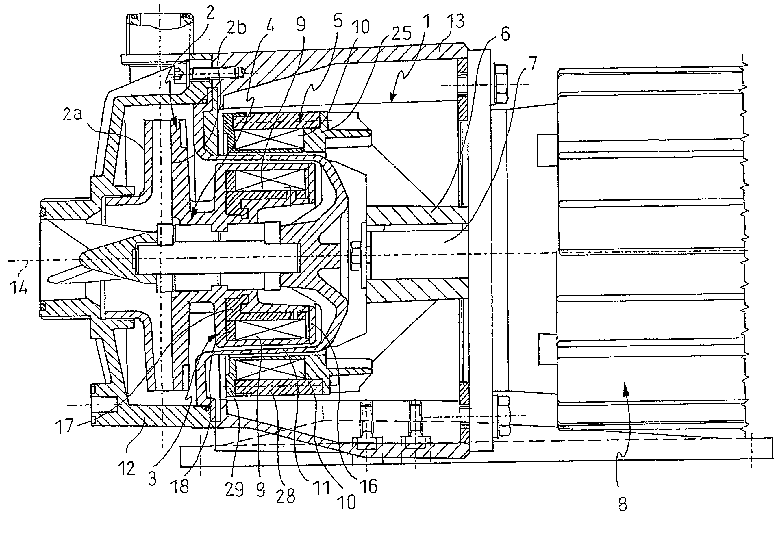
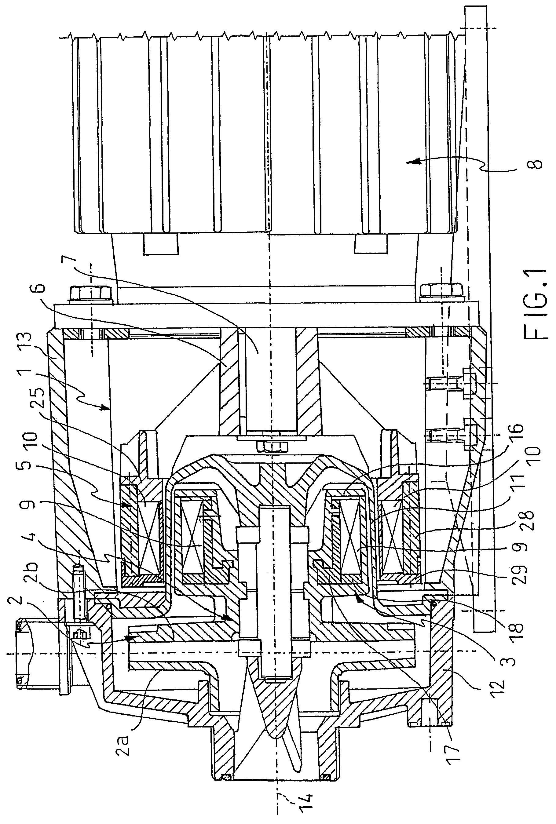
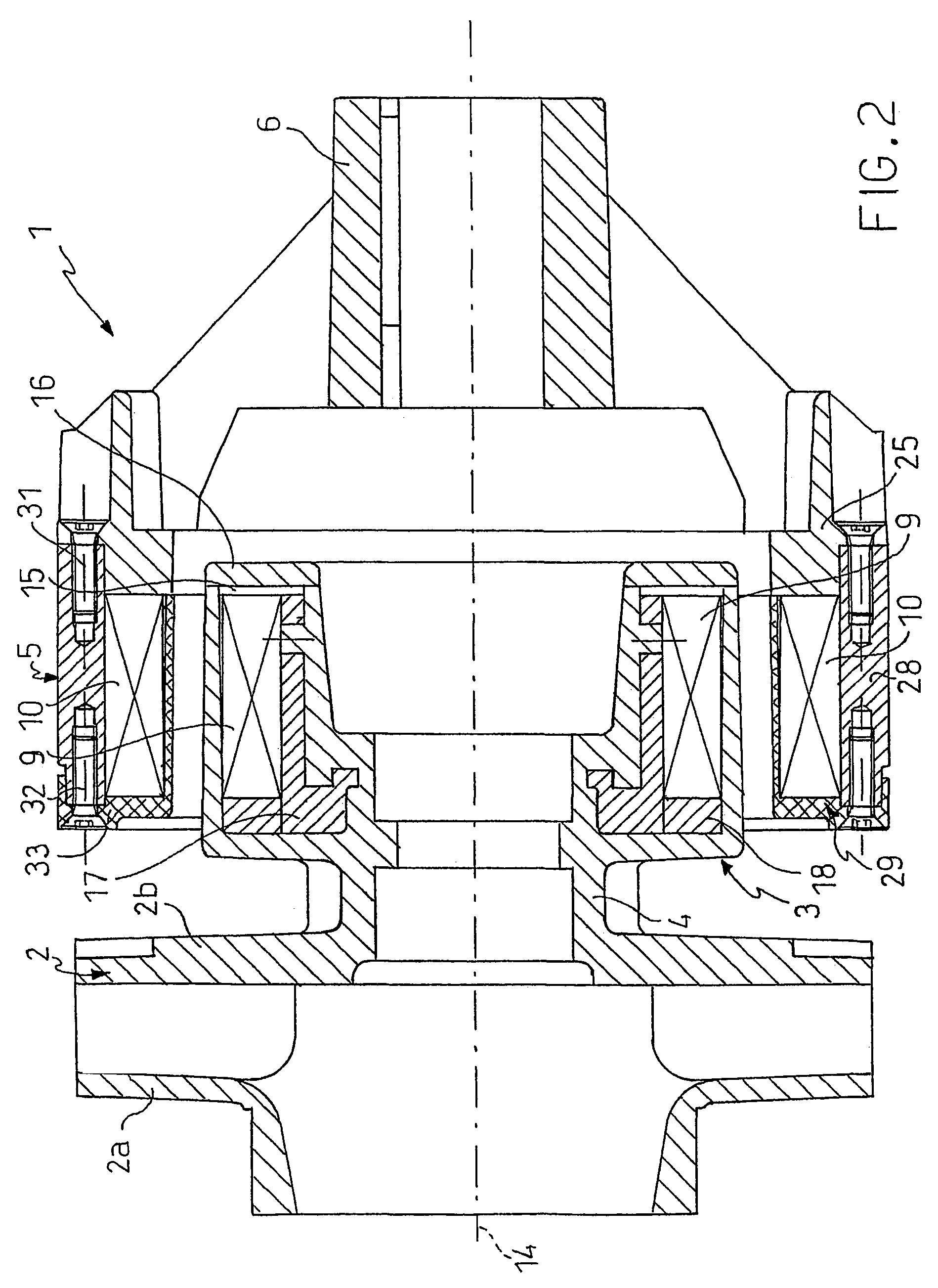
[0038]With reference to the drawings, a mechanical drive system operating by magnetic force, hereinafter also defined simply as a drive system, is generally indicated 1, and an impeller of a centrifugal pump which the system is preferably used to drive, is indicated 2.

[0039]A driven element forming part of the drive system 1 is indicated 3. The driven element 3 is fixed to a driven shaft 4 which terminates in the pump impeller 2.

[0040]A driving element forming part of the drive system 1 is indicated 5. The driving element 5 is fixed to a hub 6 to which a drive shaft 7, driven, for example, by an electric motor 8, is keyed.

[0041]Both of the elements 3 and 5 of the magnetic drive system 1 have a hollow cylindrical configuration. In particular, the driving element 5 has a larger diameter than the driven element 3 so that the latter can be positioned coaxially inside the driving element 5.

[0042]The driven element 3 has a set of driven magnets 9 and the driving element 5 has a set of dri...


PUM


Abstract

A mechanical drive system operating by magnetic force, to be fitted on a pump, comprises a basic structure on which a drive shaft, which extends along a longitudinal axis, is supported rotatably. A driving element operatively connected to the drive shaft is provided with driving magnets arranged in a ring. A driven element provided with driven magnets arranged in a ring is also mounted on the basic structure. A bell is inserted between the driving element and the driven element and isolates the environment containing the driven element. The driving element and the driven element comprise respective cages each having seats for housing the respective driving magnets or driven magnets.

Description

FIELD OF THE INVENTION[0001]The subject of the present invention is a mechanical drive system operating by magnetic force, comprising a basic structure, a drive shaft supported rotatably on the basic structure and defining a longitudinal axis, a driving element operatively connected to the drive shaft and provided with driving magnets, and a driven element mounted on the basic structure and provided with driven magnets.[0002]Further subjects of the present invention are a magnet for a drive system of the type specified above and a method of producing a mechanical drive system operating by magnetic force in which a driving element provided with driving magnets is produced, a driven element provided with driven magnets is produced, and the driving element and the driven element are mounted on a basic structure, the driving magnets facing the driven magnets in order to transmit the drive from the driving element to the driven element.[0003]According to a further aspect, a subject of th...

Claims


Application Information

Patent Timeline
IPC IPC(8): H02K49/00F04B17/00H02K1/30F04D13/02H02K1/27H02K5/128H02K49/10
CPCH02K1/278H02K1/2786H02K5/128F04D13/026F04D13/027H02K49/106Y10T464/30H02K1/2791
Inventor ABORDI, MAURIZIOCERIZZA, ALBERTO
Owner C D R POMPE
Why Eureka
Try Eureka