Noise suppression method for wave filter

a wave filter and noise suppression technology, applied in piezoelectric/electrostrictive/magnetostrictive devices, piezoelectric/electrostriction/magnetostriction machines, electrical equipment, etc., to achieve the effect of reducing only partially the energy of transverse spikes and removing abnormal signals

Active Publication Date: 2006-06-06
IND TECH RES INST
View PDF8 Cites 78 Cited by
  • Summary
  • Abstract
  • Description
  • Claims
  • Application Information

AI Technical Summary

Benefits of technology

[0007]Another objective of the present invention is to provide a noise suppression method for a wave filter, which completely eliminates the abnormal signals, such as the transverse propagating acoustic waves, caused by the transverse-mode higher harmonics vibration without the need to change to the shape of the acoustic resonant cavity.
[0008]In order to achieve the above objectives, the present invention provides a noise suppression method for wave filter; the method arranges a plurality of scatterers in the FBARs, by utilizing the characteristics variation between the scatterers and the thin film bulk material, an band gap similar to the band gap of photonic crystals, called phononic band gap, can be created. These scatterers produce a destructive interfering effect to transverse higher harmonics vibration within the operating frequency range, thus any transverse propagating acoustic waves, whether it is the wave vector or the resonant mode thereof, cannot exist in the operating frequency range. Therefore, the present invention can completely eliminate abnormal signals created by any transverse mode; unlike the prior art, where energy of the transverse spikes is only partly reduced.

Problems solved by technology

These scatterers produce a destructive interfering effect to transverse higher harmonics vibration within the operating frequency range, thus any transverse propagating acoustic waves, whether it is the wave vector or the resonant mode thereof, cannot exist in the operating frequency range.

Method used


Image

  • Noise suppression method for wave filter
  • Noise suppression method for wave filter
  • Noise suppression method for wave filter

Examples


Embodiment Construction

[0015]The descriptions below of specific embodiments are to illustrate the present invention. Others skilled in the art can easily understand the advantages and effectiveness of the present invention from contents disclosed in this specification. The present invention can be carried out or applied through other different embodiments. Every details of this specification can be modified based on different viewpoints and applications yet still within the scope of the present invention, for example, modify the arrangement or position of the scatterers etc.

[0016]Embodiments below further describe the viewpoints of the present invention, but it is not intended in any way to limit the scope of the present invention.

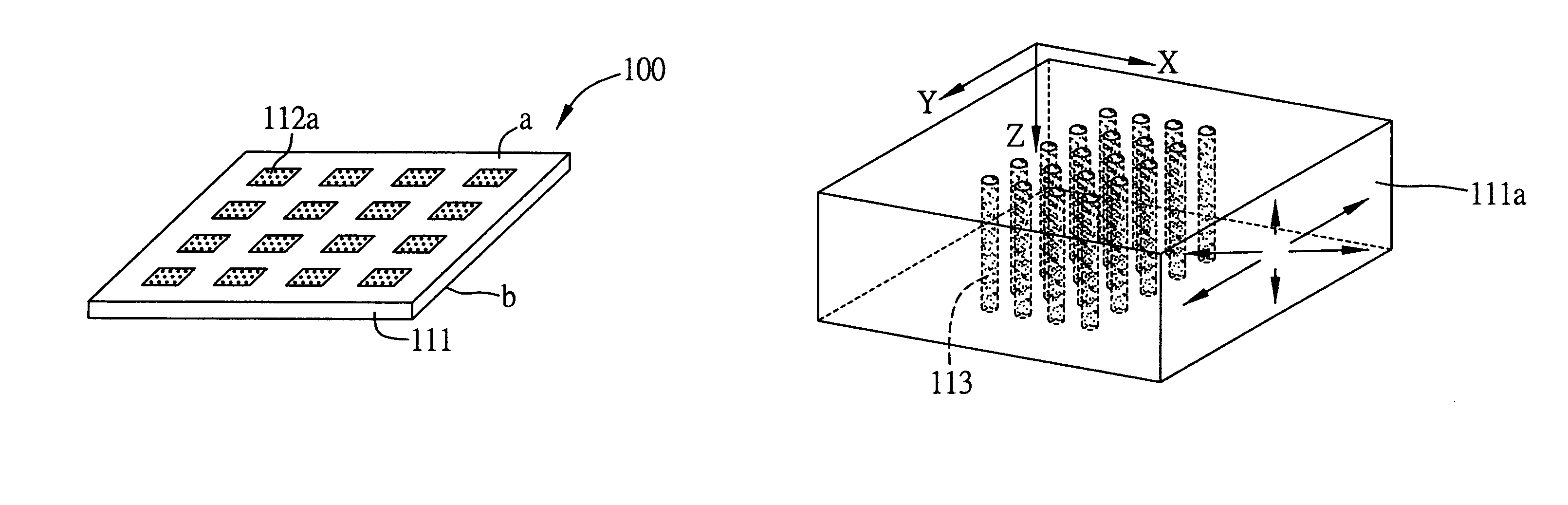
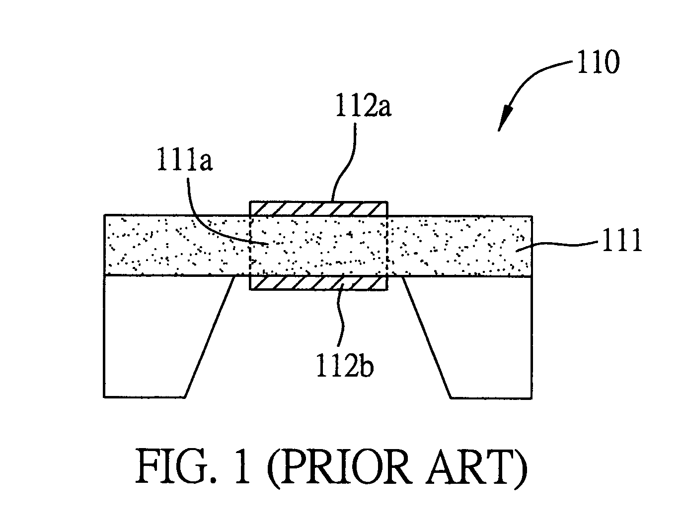
[0017]In the following embodiments, the noise suppression method of the present invention is applied in a thin film bulk acoustic wave filter, in order to eliminate the abnormal signals generated by the transverse wave propagating modes in the film bulk acoustic wave filter, as ...


PUM


Abstract

A noise suppression method of a wave filter used to eliminate standing wave signal interferences in the acoustic wave filter consisted by a plurality of film bulk acoustic resonators (FBARs). The method is to provide a plurality of scatterers in the structured consisted by the FBARs, thereby creating an band-gap structure due to the material characteristics difference, which consequently generates a destructive interfering effect to the transverse higher harmonics vibration within a specific operating frequency range, and ultimately decreases or even eliminates any parasitic effects. Therefore, within the operation frequency range of this band-gap structure, abnormal signals created by any transverse wave modes cannot exist. In addition, an acoustic shield can be provided by phononic crystal structures between different FBARs, thus acoustic shielding any mutual interference within the operation frequency range.

Description

FIELD OF THE INVENTION[0001]The present invention relates to a noise suppression technique, and more particularly, to a noise suppression method that forms a plurality of scatterers in the structure of film bulk acoustic resonators, thereby allowing destructive interfering effect to be applied to transverse higher harmonics vibration due to the band-gap structure generated by characteristics difference between materials used.DESCRIPTION OF THE PRIOR ART[0002]For conventional crystal wave filters used in VHF and HF bands under 300 MHz, the upper limit of operating frequency is mainly restricted by accuracy of the crystal thickness thinning process, which suppresses the rising of operating frequency. Nowadays, micro-electro-mechanical system (MEMS), combined with accurate control of sputtering film thickness, are used to obtain crystal-filer-structure alike thin Film Bulk Acoustic Resonators (FBARs), the resonant frequency of which can be raised to several GHz to tens of GHz. In recen...

Claims


Application Information

Patent Timeline
Patent Type & Authority Patents(United States)
IPC IPC(8): H03H9/15H03H9/54H03H9/00H03H9/02H03H9/17H03H9/46
CPCH03H9/02118H03H9/0211
Inventor HWU, KEH-LONG
Owner IND TECH RES INST
Why Eureka
Try Eureka