Atmospheric turbulence resistant open-air optical communication system

a technology of optical communication system and atmospheric turbulence, which is applied in the direction of transmission monitoring, transmission monitoring/testing/fault-measurement system, electrical equipment, etc., can solve the problems of loss of signal strength, hampered development of such systems, and inability to solve the basic limitations imposed by the laws of physics

Inactive Publication Date: 2001-06-05
OPTICAL SCI
View PDF4 Cites 16 Cited by
  • Summary
  • Abstract
  • Description
  • Claims
  • Application Information

AI Technical Summary

Problems solved by technology

Despite significant advances in the field of open-air optical communication, the development of such systems has been hampered by certain basic, underlying effects upon open-air optical communication systems that are unique to this type of communication.
A collimated beam broadens due to the scattering, thus resulting in losses in signal strength.
Essentially, there is no simple solution to overcome the basic limitations imposed by the laws of physics.
However, even in clean air conditions, atmospheric turbulence-induced

Method used


Image

  • Atmospheric turbulence resistant open-air optical communication system
  • Atmospheric turbulence resistant open-air optical communication system
  • Atmospheric turbulence resistant open-air optical communication system

Examples


Embodiment Construction

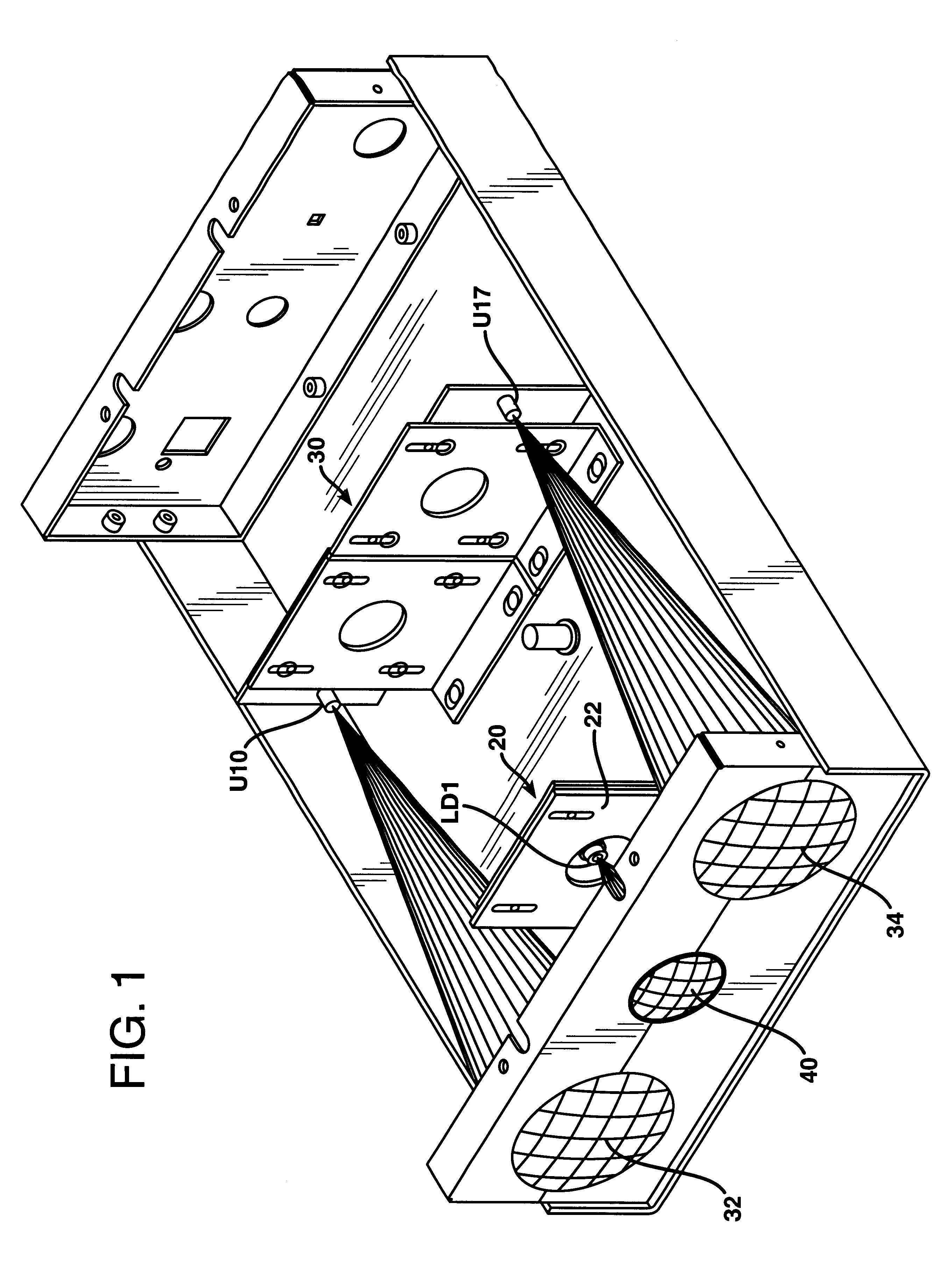
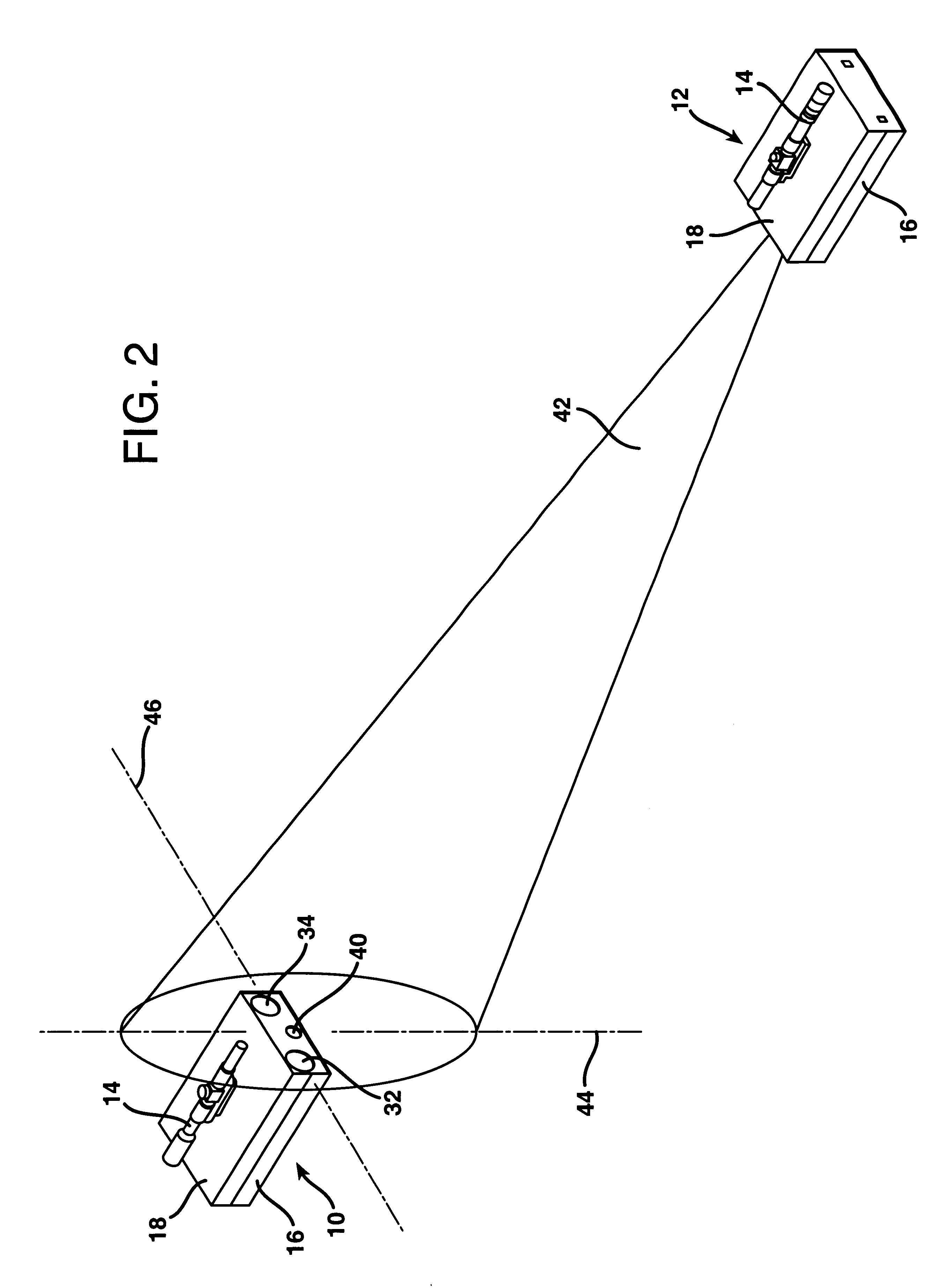
As illustrated in FIG. 2, a full duplex open-air optical communication system according to the invention may be constructed utilizing a pair of optical transceiver units 10 and 12. The transceivers 10 and 12 are identical in all respects and are positioned in optical combination to transmit and receive signals to and from each other. The electronic and optical components of the transceivers 10 and 12 are each housed within a weather-resistant case 16 having a cover 18 seated thereon in a weather-tight fashion. FIG. 1 illustrates one of the optical transceivers 10 or 12 with the cover 18 removed therefrom.

The physical dimensions of the case 16 of each of the transceivers 10 and 12 is one hundred millimeters in height, one hundred eighty millimeters in width, and two hundred ninety millimeters in depth. The system employs a 12-volt DC nominal power supply and may be operated between 0.degree. C. to 50.degree. C. Each of the transceivers 10 and 12 weighs 1.5 kg.

As illustrated in FIG. 1...


PUM


Abstract

An open-air optical communication system is provided which enhances accuracy and reliability of signal transmission by utilizing multiple optical receivers. Two or more receivers are positioned within the path of a collimated optical beam emitted by a remote transmitter. The receiving lenses are of equal size and are positioned apart in a plane perpendicular to the optical beam a distance at least as great as the receiving lens diameter. The receiving lenses thereby receive two or more signals through different optical paths. All of these signals are electronically combined to yield one composite received signal that is better than any one of the individual received signals. The system employs automated gain control circuitry to further eliminate any signal fluctuations caused by atmospheric phenomena such as turbulence, fog, smoke, dust, rain, snow, etc. By utilizing multiple receivers, degradation of the transmitted signal due to atmospheric turbulence induced optical scintillation is significantly reduced.

Description

1. Field of the InventionThe present invention relates to an open-air optical communication system that avoids signal degradation due to attenuation and scattering.2. Description of the Prior ArtOpen-air optical communication systems have been available for decades and cover the range from single RS-232 units operating at 1200 bps to high-speed ATM units capable of live video broadcasts. While all conventional optical communication systems operate with weather related constraints, continuing advances in bandwidth improvement, cost reductions, and the minimization of atmospheric affects have aided in bringing optical communication systems into the mainstream of communication products available to the telecommunications engineer. Exemplary developments in this regard are reported in the following recent technical papers: T. Wang, G. R. Ochs, and S. F. Clifford, A Saturation-resistant Optical Scintillometer to Measure C.sub.n.sup.2, J. Opt. Soc. Am. 68, 334 (1978); S. F. Clifford, G. R...

Claims


Application Information

Patent Timeline
IPC IPC(8): H04B10/10
CPCH04B10/1121
Inventor WANG, TING-I
Owner OPTICAL SCI
Why Eureka
Try Eureka