Camera system that compensates low luminance by composing multiple object images

a camera system and image technology, applied in the field of single picture image camera system, can solve the problem that the image flow cannot be obtained by the camera system, and achieve the effect of low noise component, high quality and low noise componen

Inactive Publication Date: 2006-06-06
MINOLTA CO LTD
View PDF22 Cites 151 Cited by
  • Summary
  • Abstract
  • Description
  • Claims
  • Application Information

AI Technical Summary

Benefits of technology

[0008]A purpose of this invention is to provide a camera system by which a high quality and properly exposed picture image can be obtained without using a flash light when an illuminance of an image is lower.
[0010]By such a configuration, each image data has no error component of image flow due to a camera shake, since the image data is taken by the image pickup device during the integration time shorter than the limit integration time causing the camera shake. The picture image formed by the composition of the image data has a low noise component, since it is not formed by an amplification of low S / N image data. As a result, a high quality picture image having a low noise component and no image flow can be obtained by the camera system.

Problems solved by technology

As a result, a high quality picture image having a low noise component and no image flow can be obtained by the camera system.

Method used


Image

  • Camera system that compensates low luminance by composing multiple object images
  • Camera system that compensates low luminance by composing multiple object images
  • Camera system that compensates low luminance by composing multiple object images

Examples


first embodiment

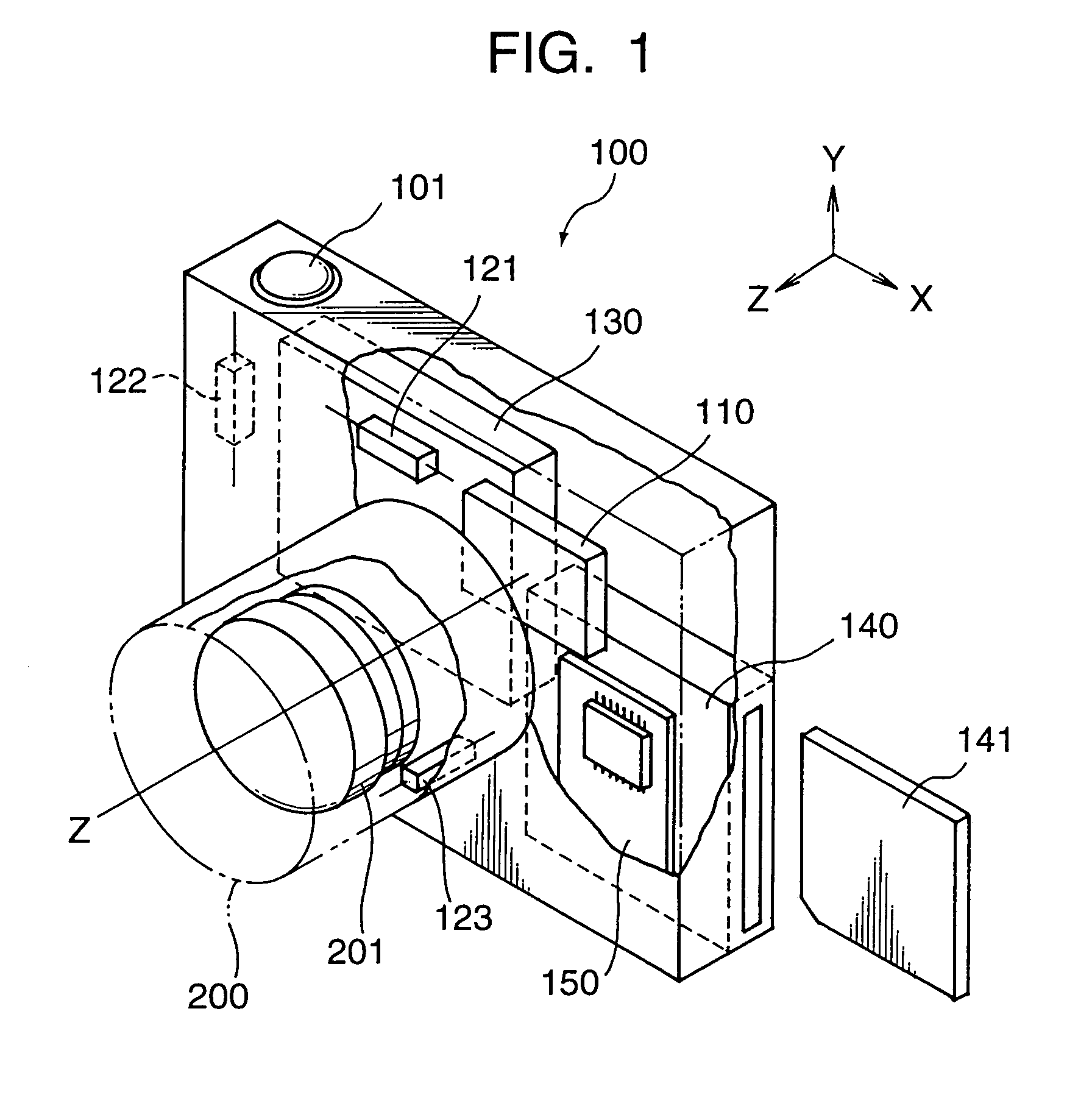
[0032]A first embodiment of this invention is described. A configuration of a digital camera in the first embodiment and an arrangement of elements constituting the digital camera are shown in FIG. 1.

[0033]As can be seen from FIG. 1, a taking lens unit 200 is provided substantially at the center of a body of a digital camera 100. The taking lens 200 is not necessarily an interchangeable one. Furthermore, a focal length of an optical lens system 201 of the taking lens unit 200 is not necessarily variable. Focusing of the optical lens system 201 can be adjusted by manual or automatic.

[0034]An image pickup device such as CCD 110 is disposed on an optical axis Z (which is called Z-axis, too) and in the vicinity of a focal plane of the optical lens system 201. The image pickup device 110 is substantially the same as one widely used in a video camera with shake correction function. As shown in FIG. 3, the image pickup device 110 has an effective photosensing region illustrated by solid li...

second embodiment

[0120]A second embodiment of this invention is described with reference to the figures. A configuration and an arrangement of the elements of the digital camera in the second embodiment are substantially the same as those of the above-mentioned first embodiment, so that the explanations of the common configurations are omitted.

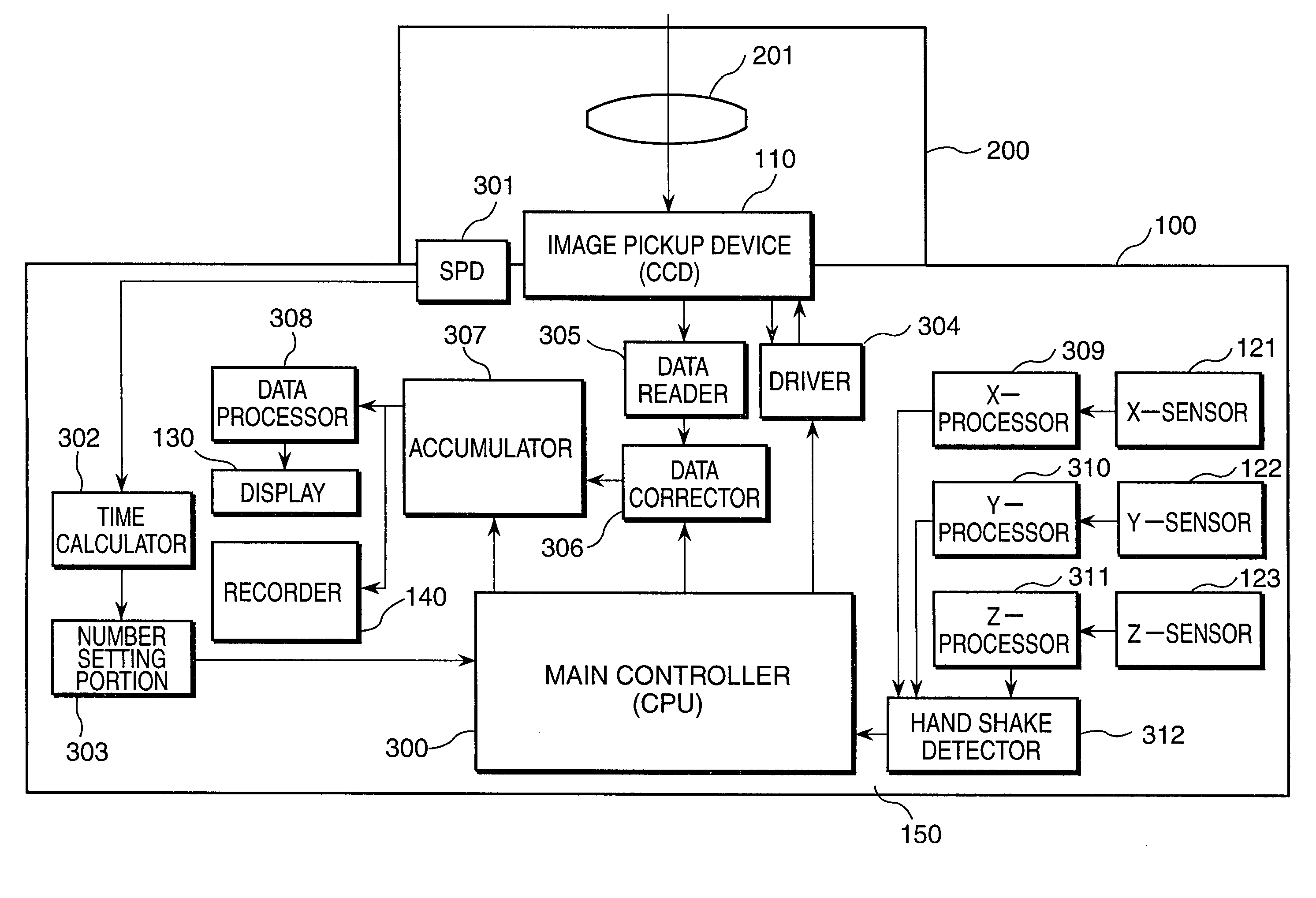
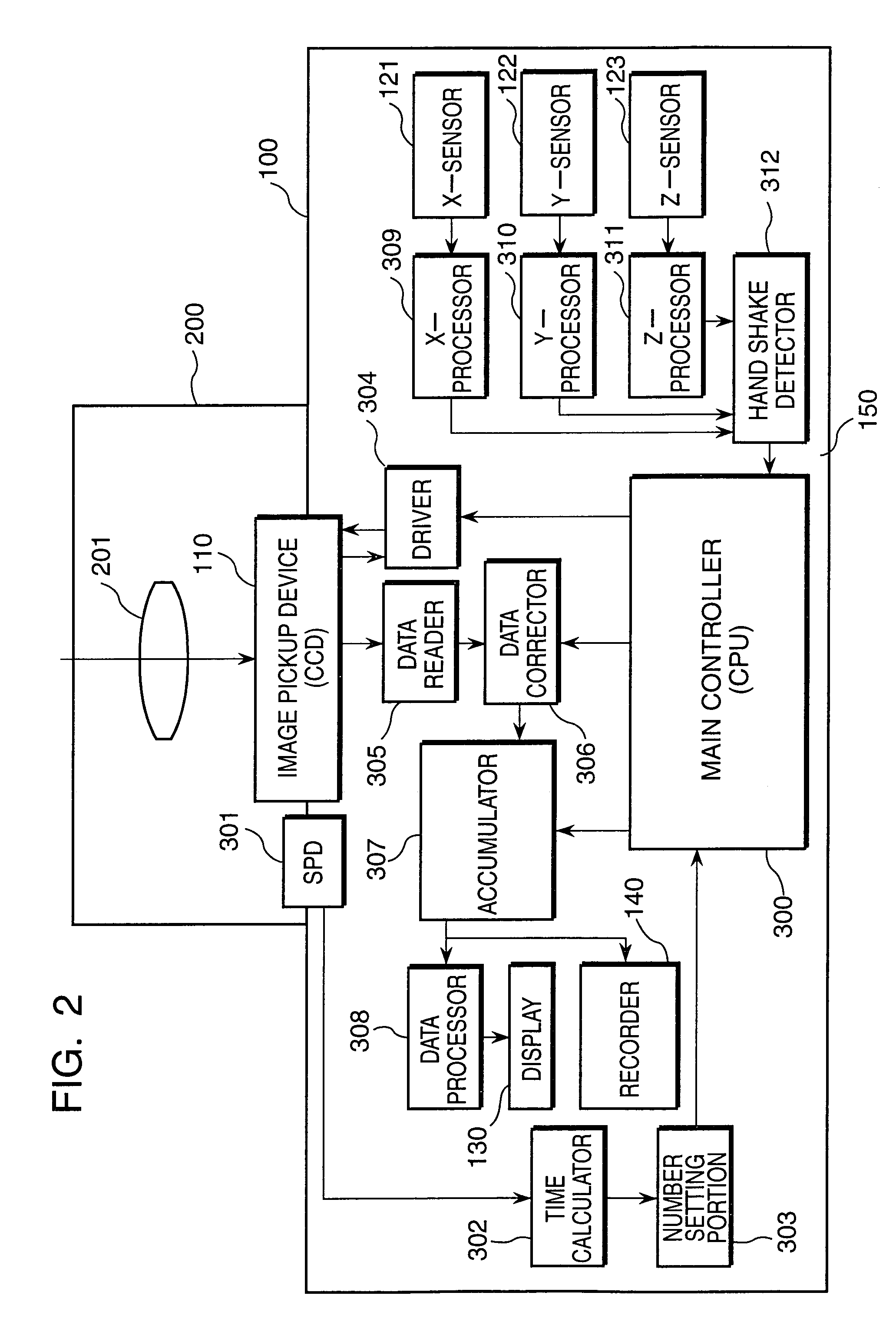
[0121]A block diagram of a control circuit 150 in the second embodiment is shown in FIG. 15. In the above-mentioned first embodiment, when the image data is taken on and after the second image pickup operation, the image data is corrected soon by the image data corrector 306 and the corrected image data are accumulated in the image data accumulator 307. In the second embodiment, the image data taken on and after the second image pickup operation are memorized temporally in an image data memory portion 314, and results of camera shake detection are also memorized in a camera shake memory portion 313.

[0122]When a predetermined number of image data are taken, the...


PUM


Abstract

In a digital camera using an image pickup device such as CCD, a high resolution and properly exposed image is obtained by composition a plurality of image data of the same object taken by a plurality of image pickup operation when a luminance of the object is lower. Each image data is taken under a condition that an integration time (a charge storage time) of the image pickup device is shorter than a limit integration time causing a camera shake. A position of a frame on the image pickup device from which electric charges of the pixels are read out as the image data is corrected so as to cancel the movement of the camera between the image pickup operations.

Description

[0001]This application is based on patent application Hei.11-024842 filed in Japan, the contents of which are hereby incorporated by references.BACKGROUND OF THE INVENTION[0002]1. Field of the Invention[0003]This invention relates to a camera system for forming a single picture image by a composition of a plurality of image data of the same object which are taken by an image pickup device such as CCD (Charge Coupled Device).[0004]2. Description of the Related Art[0005]In a conventional digital camera for taking a still picture image by using an image pickup device, when a luminance of an image is lower and a flash light is not used, a charge storage time for storing electric charge in each pixel of the image pickup device (hereinafter, abbreviated as integration time) is lengthened for adjusting a brightness of an image displayed on a monitor display. Alternatively, an amplification factor for amplifying output signals from the image pickup device is increased for adjusting the brig...

Claims


Application Information

Patent Timeline
Patent Type & Authority Patents(United States)
IPC IPC(8): H04N5/228G03B17/00G06K9/32H04N5/225G03B5/00H04N5/232H04N5/235H04N5/243H04N5/335H04N5/351H04N5/353H04N5/372
CPCG03B5/00H04N5/23248H04N5/2355H04N5/23277H04N5/235H04N5/23274G03B2217/005H04N23/68H04N23/6842H04N23/6845H04N23/70H04N23/741
Inventor HARA, YOSHIHIROKOSAKA, AKIRA
Owner MINOLTA CO LTD
Why Eureka
Try Eureka