Imaging method for a multi-slice spiral CT scan with 3D reconstruction, and a computed tomography unit for carrying out this method

a multi-slice spiral, computed tomography technology, applied in tomography, instruments, nuclear engineering, etc., can solve problems such as image quality loss, and achieve the effect of high image quality

Inactive Publication Date: 2006-06-06
SIEMENS HEALTHCARE GMBH
View PDF8 Cites 14 Cited by
  • Summary
  • Abstract
  • Description
  • Claims
  • Application Information

AI Technical Summary

Benefits of technology

[0006]It is therefore an object of an embodiment of the invention to find a 3D reconstruction method in which the direction of filtering is selected optimally in order to achieve high image quality.

Problems solved by technology

This mode of procedure is attended by the problem that because the collected data, which are firstly projected, for the purpose of simplifying calculation, onto a virtual detector—which lies on a plane that intersects the axis of rotation of the real detector and radiation source—are present in two dimensions and the filtering is intended to take place only in one dimension because of the resultant outlay on computation, there is no preferred direction to be seen in which the filtering should take place.
If an unfavorable filtering direction is selected, it is therefore accompanied by losses in image quality.

Method used


Image

  • Imaging method for a multi-slice spiral CT scan with 3D reconstruction, and a computed tomography unit for carrying out this method
  • Imaging method for a multi-slice spiral CT scan with 3D reconstruction, and a computed tomography unit for carrying out this method
  • Imaging method for a multi-slice spiral CT scan with 3D reconstruction, and a computed tomography unit for carrying out this method

Examples


Embodiment Construction

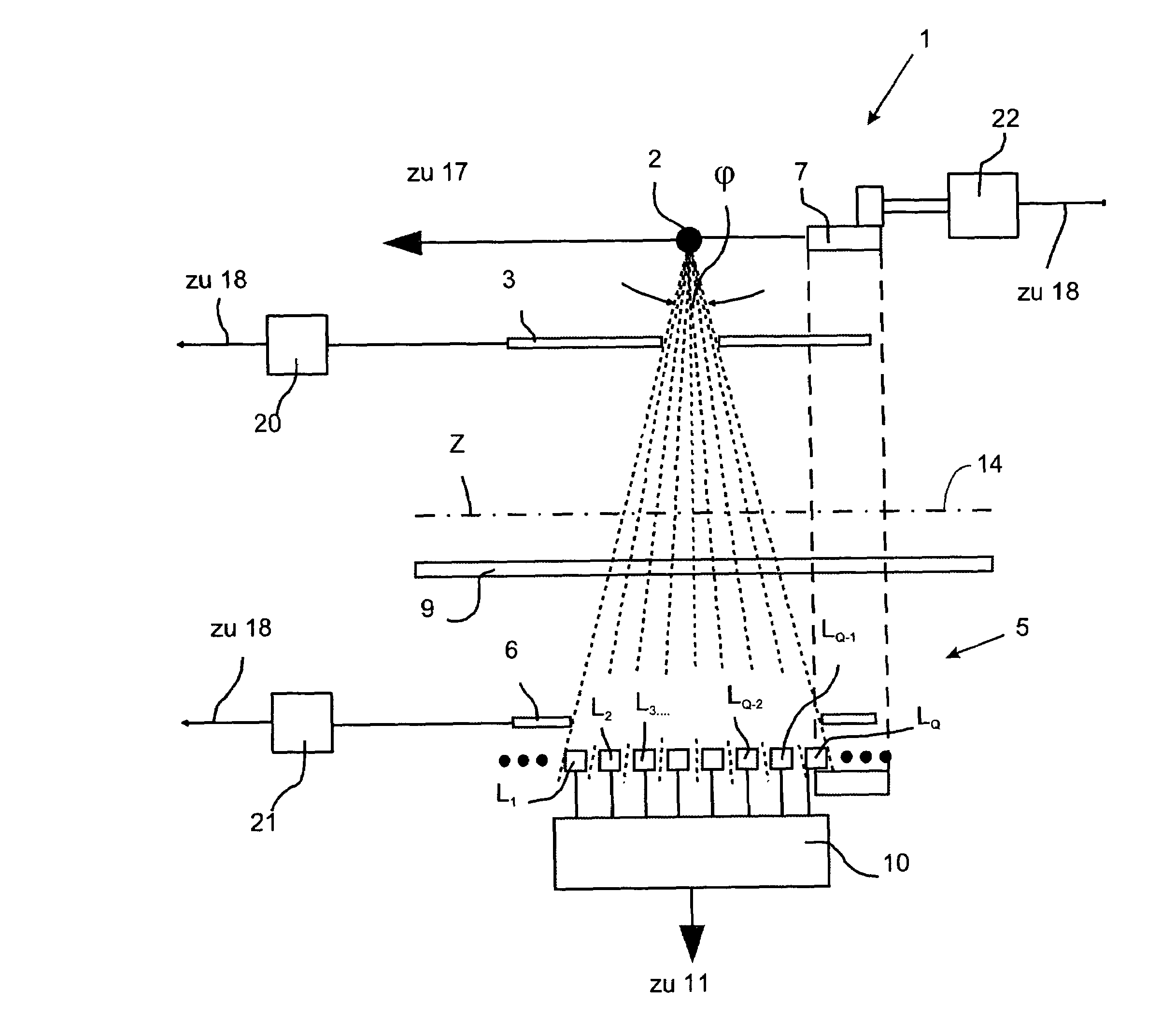
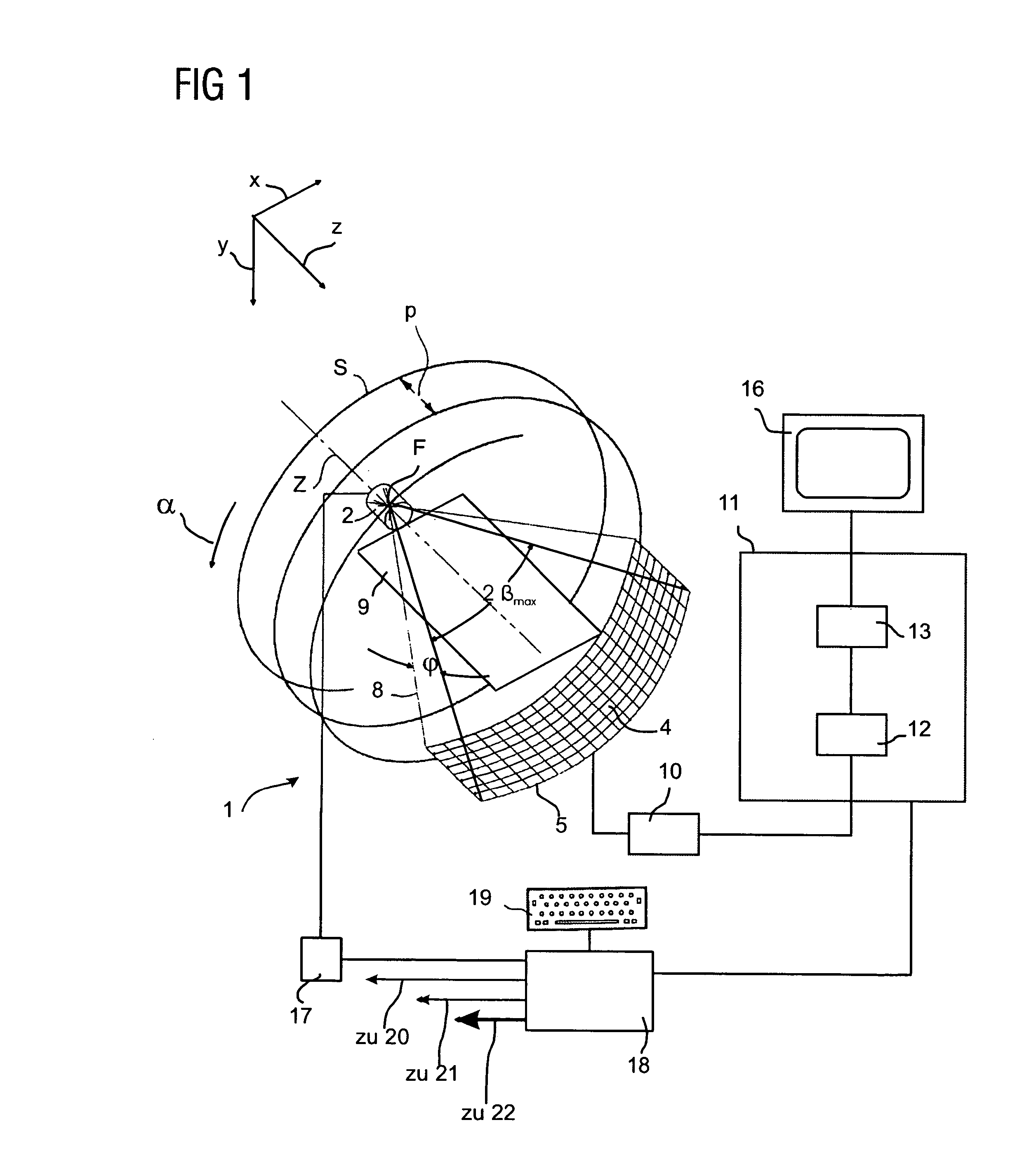
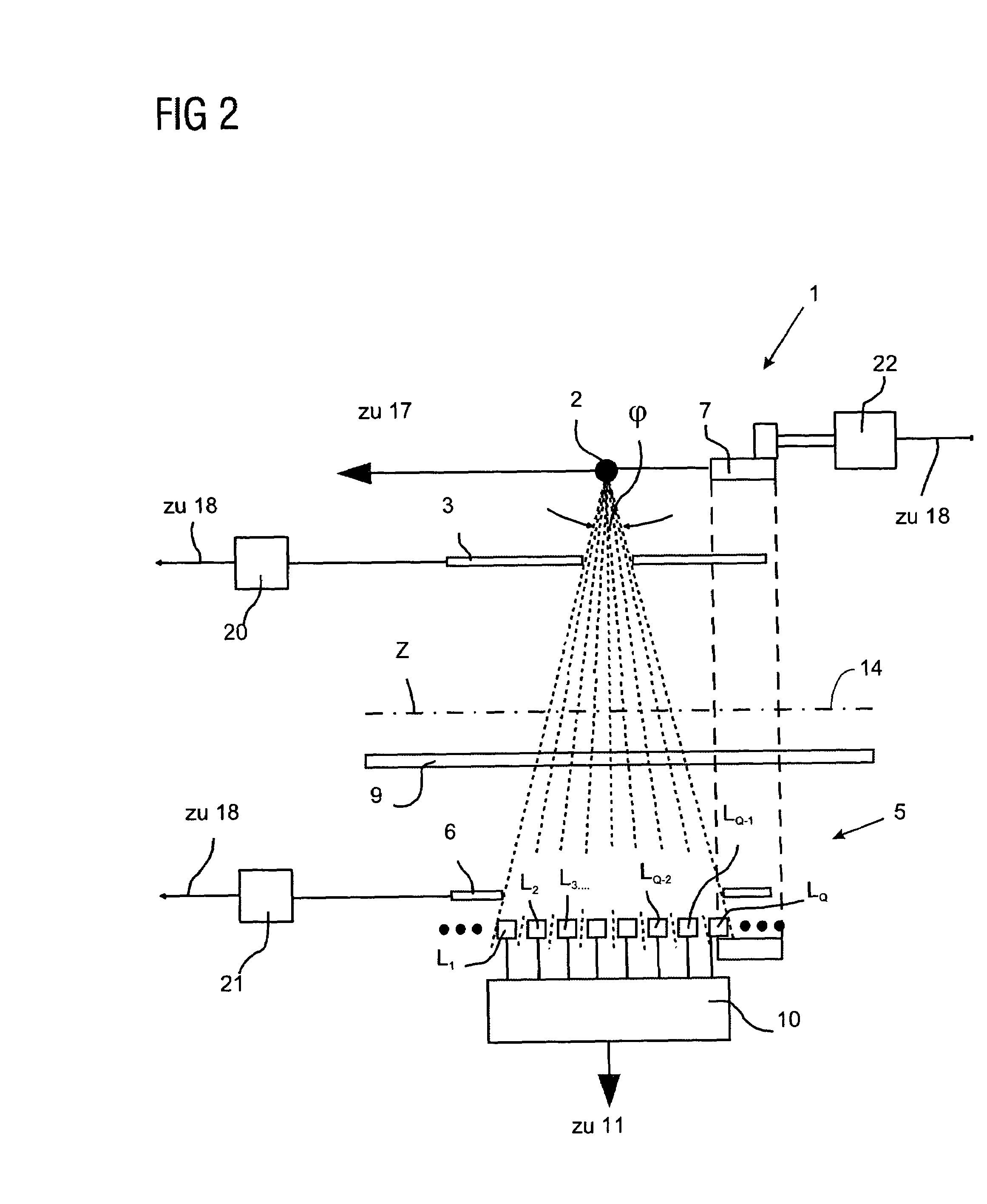
[0037]FIGS. 1 and 2 show a partially perspective illustration of a third generation multi-slice CT unit for carrying out the method according to an embodiment of the invention. The measuring arrangement (=gantry) denoted by 1 has an X-ray source 2 with a beam diaphragm 3 positioned in front of it. This array of planar design having a plurality of rows and columns of detector elements forms a detector system 5 and is illustrated in section in FIG. 2 with a beam diaphragm 6 positioned in front of said detector system and near the detector. For the purpose of greater clarity, FIG. 1 illustrates only eight rows L1 to LQ of detector elements 4. Detector system 5 can, however, also have any other or preferably greater number of rows without departing from the scope of the invention. A different planar arrangement of the detectors is also likewise possible.

[0038]The X-ray source 2 with the beam diaphragm 3 on the one hand, and the detector system 5 with the beam diaphragm 6, on the other h...


PUM


Abstract

An imaging method is for a multi-slice spiral CT scan with 3D back projection. Use is made, for the reconstruction of the absorption value of at least one voxel, of the measured and filtered data that are produced by rays which penetrate the at least one voxel. A CT unit is further used to carry out the method. In the method, the filtering of the data, required for the reconstruction, in the image of the virtual detector is performed in the direction of the projection of spiral segments imaged thereon which are produced by the spiral scanning over a prescribed angular range. The CT unit includes a device for carrying out directional filtering of this type.

Description

[0001]The present application hereby claims priority under 35 U.S.C. §119 on German patent application number DE 102 48 770.7 filed Oct. 18, 2002, the entire contents of which are hereby incorporated herein by reference.FIELD OF THE INVENTION[0002]The invention generally relates to an imaging method for a multi-slice spiral CT scan with 3D back projection. An object to be examined may be scanned spirally with reference to its absorption behavior by way of a rotating ray bundle moving in the direction of the axis of rotation. The measured absorption data may be collected by the detector of planar design. The measured absorption data are projected onto a virtual detector, preferably at the fulcrum of the rotation, and filtered, and for the reconstruction of the absorption value of at least one voxel use is made of those measured and filtered data that have been produced by rays which penetrate this at least one voxel. The invention also generally relates to a CT unit for carrying out ...

Claims


Application Information

Patent Timeline
Patent Type & Authority Patents(United States)
IPC IPC(8): A61B6/03G06T17/00G21K1/12
CPCA61B6/032A61B6/027A61B6/466G06T11/006G06T2211/421
Inventor BRUDER, HERBERTFLOHR, THOMASSCHALLER, STEFANSTIERSTORFER, KARL
Owner SIEMENS HEALTHCARE GMBH
Why Eureka
Try Eureka