Fluid recovery device

a technology of flue gas recovery and recovery device, which is applied in the direction of vacuum cleaners, floor scrubbing machines, carpet cleaners, etc., can solve the problems of surface stains appearing or reappearing, extractors are generally limited to a single operation direction, and extractor machines may be difficult to maneuver in some environments

Inactive Publication Date: 2006-06-13
TENNANT COMPANY
View PDF14 Cites 77 Cited by
  • Summary
  • Abstract
  • Description
  • Claims
  • Application Information

AI Technical Summary

Problems solved by technology

Additionally, carpet overwetting may cause surface stains to appear or reappear as underlying soil or stains migrate from the bottom of the carpet to its surface.
Extractors are generally limited to a single operational direction as the steps of wetting, agitation, and vacuuming are sequentially performed.
As a result, extractor machines may be difficult to maneuver in some environments, i.e., complex floor layouts.
Another common problem with known extractors includes soiled solution suspended in the extractor head.
Upon deactivation of the vacuum, the suspended soiled solution in the extractor head drops out of the head and may stain or leave an excessively wet mark.
Yet another problem with extractors is that the vacuum pressures are not evenly distributed along the width of the nozzle, resulting in uneven soiled solution extraction.
Another problem associated with extractors is that the extractor pick-up nozzle must generally have a high profile in order to provide a sufficiently uniform vacuum across its width.
This geometry makes the system somewhat unwieldy and difficult to use in small or tight spaces.

Method used


Image

  • Fluid recovery device
  • Fluid recovery device
  • Fluid recovery device

Examples


example

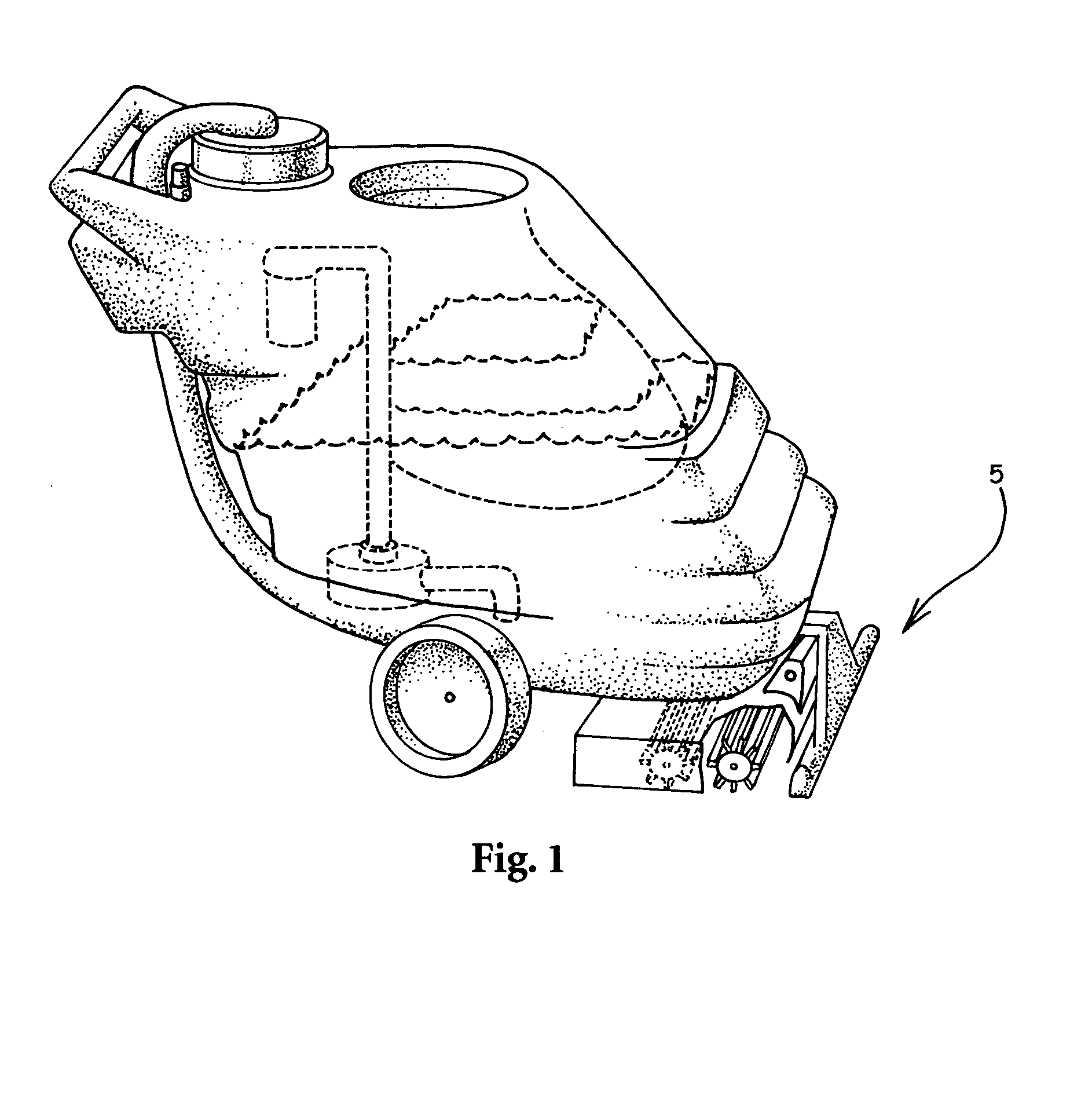
[0046]The recovery rate of the low-profile push-pull pick-up head of the present invention was compared to a standard, high-profile pick-up head on a Power Eagle extractor, Model Number 1016, manufactured by Tennant Company. The recovery rate was defined as a ratio, expressed as a percentage of the amount of solution extracted from the surface to the amount of solution applied to the surface. A higher recovery rate results in a drier carpet since less water remains in the carpet after using the extractor.

[0047]The extractor was used on a test table carpeted with level loop carpeting at two different speeds, measured in inches per second, with each type of pick-up head. The extractor was also tested on an actual office floor carpeted with a different level loop carpeting at a higher speed. A measured volume of water was poured onto each test surface, the extractor was used on the surface, and the volume of water removed by the extractor was compared to the initial volume of water app...


PUM


Abstract

An apparatus and method for extracting soiled cleaning solution from carpets and other surfaces utilizing a low-profile pick-up head is disclosed. The apparatus includes a vacuum chamber or enclosed space positioned in a fluid recovery device to provide a uniform vacuum along the entire width of the device. Also disclosed is a low-profile push-pull fluid recovery device which includes a positive pressure chamber and a vacuum chamber in the push-pull head to distribute positive and vacuum pressures, respectively, along the width of the push-pull head. Methods for using such pick-up heads are also disclosed.

Description

FIELD OF THE INVENTION[0001]The present invention is directed to floor surface maintenance systems, and especially to the maintenance of carpeted areas by using such maintenance systems.BACKGROUND OF THE INVENTION[0002]In general, proper carpet maintenance involves regular vacuuming and periodic cleaning to remove soil by methods such as hot water extraction, shampooing, bonnet cleaning, foam cleaning, etc. Some of the soil is loosely found between carpet fibers while other soil is held upon the carpet fibers by some means such as electrostatic forces, van der Waals forces, or oil bonding. Still other soil is mechanically trapped by carpet fibers. Regular vacuuming is essential as it removes some of the loose soil that damages the fibers. Vacuuming maintains the surface appearance of a carpet and keeps the level of soil in the pile at an acceptable level. Vacuuming removes only particulate soil and some unbound or loosely bound surface dirt; therefore, other methods of cleaning are ...

Claims


Application Information

Patent Timeline
Patent Type & Authority Patents(United States)
IPC IPC(8): A47L11/30A47L9/02A47L9/08
CPCA47L9/02A47L11/4044A47L11/30A47L9/08
Inventor WYDRA, LARRY D.BROS, DAVID E.
Owner TENNANT COMPANY
Why Eureka
Try Eureka