Method and device for full thickness resectioning of an organ

Inactive Publication Date: 2006-06-13
BOSTON SCI SCIMED INC
View PDF10 Cites 1472 Cited by
  • Summary
  • Abstract
  • Description
  • Claims
  • Application Information

AI Technical Summary

Benefits of technology

[0007]The present invention is directed to a full-thickness resection system comprising a flexible endoscope and a stapling mechanism, wherein the endoscope is slidably received through at least a portion of the stapling mechanism. The stapling mechanism includes an anvil and a stapling head mounted to the anvil so that the anvil and the stapling head are moveable with respect to one another between a tissue receiving position and a stapling position and wherein a gap formed between the stapling head and the anvil is larger in the tissue receiving position than it is

Problems solved by technology

For example, several known resection devices and procedures requires at least one incision in an area near the portion of the organ to be excised for access to the lesion or treatment site (because, for example, the resectioning device may lack steering and/or viewing capabilities).
Of course, these incisions are painful and may involve a partial or entire loss of mobility while recuperating from the incision, in addition to recovering from the tubular resectioning procedure itself.
In addition, the time required to recover from such a procedure is often longer than for procedures which do not require incisions.
Thus, this type of resectioning procedure involves the drawbacks mentioned above in regard to procedures requirin

Method used


Image

  • Method and device for full thickness resectioning of an organ
  • Method and device for full thickness resectioning of an organ
  • Method and device for full thickness resectioning of an organ

Examples


first embodiment

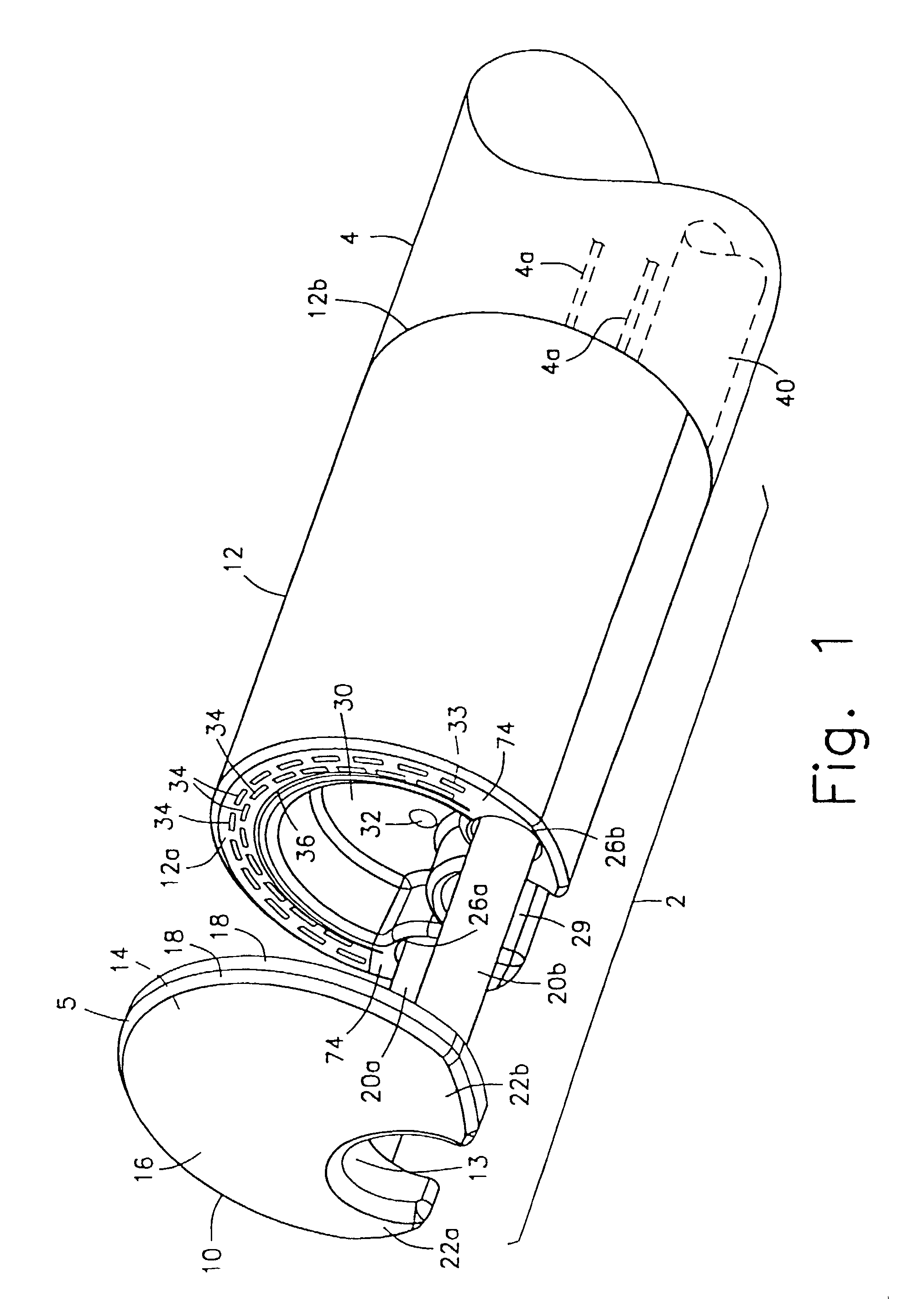
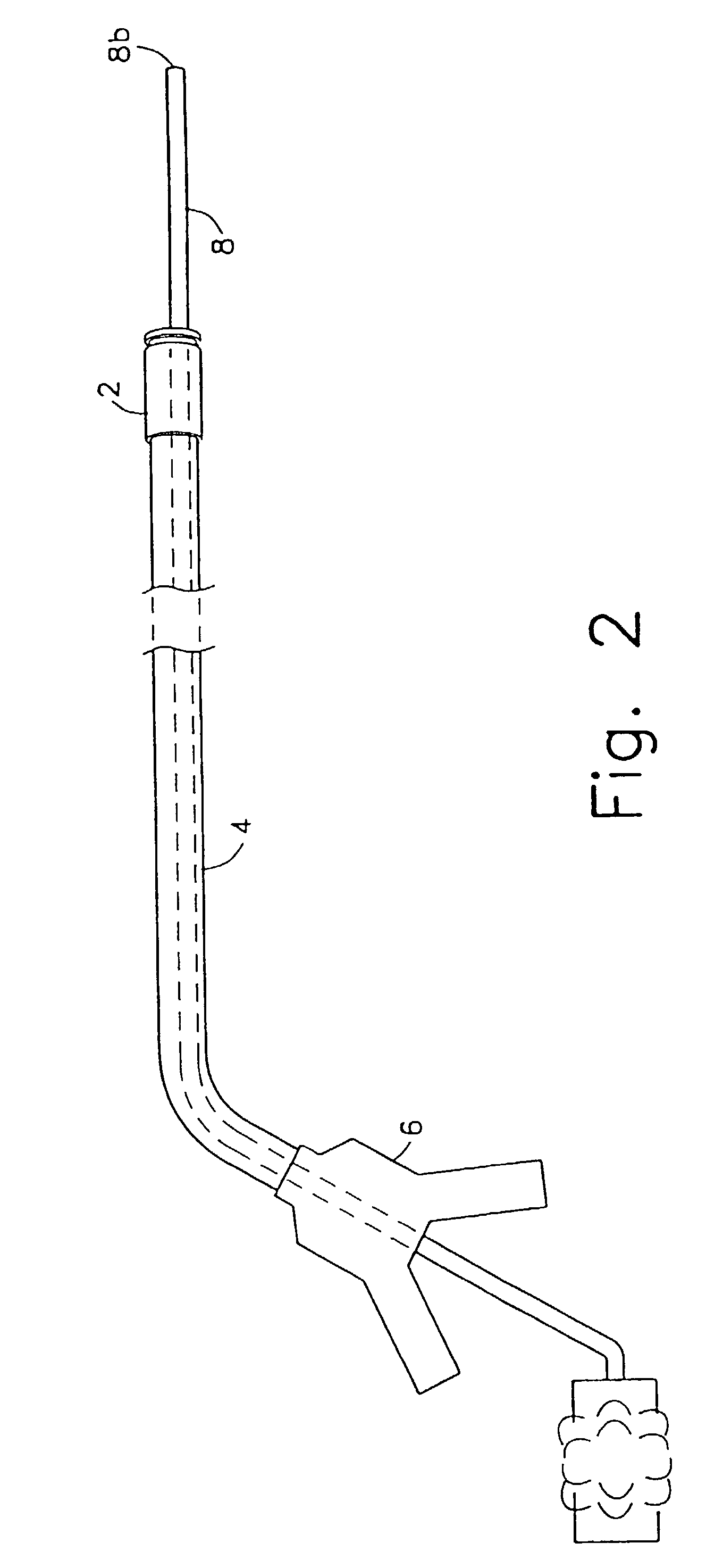
[0043]As shown in FIGS. 1 and 2, an apparatus according to the present invention comprises a working head assembly 2 which may preferably be connected to a distal end 4a of a sheath 4. The proximal end 4b of the sheath 4 may preferably be connected to a control handle 6.

[0044]In operation, the entire apparatus is mounted onto an endoscope 8 by passing the endoscope 8 through the control handle 6, the sheath 4, and the working head assembly 2, as shown in FIG. 2. The endoscope 8 is then inserted into a body orifice to locate a lesion in the tubular organ under visual observation (usually while insufflating the organ). Once the lesion has been located, the working head assembly 2 and the sheath 4 are slidably advanced along the endoscope 8 into the tubular organ until the working head assembly 2 is in a desired position adjacent to the lesion. Those skilled in the art will understand that in an alternative embodiment, the working head assembly 2 may also be detachably coupled to a dis...

second embodiment

[0077]FIG. 11 shows a device according to the present invention in which like reference numerals identify the same elements.

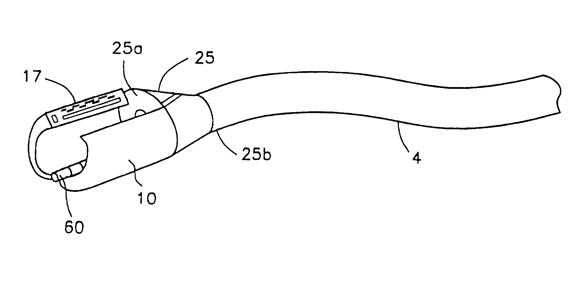
[0078]The anvil member 10 of this embodiment preferably has a substantially circular or elliptical cross-section and is gradually tapered from the proximal face 14 to its distal end 16, forming a bullet-like structure. This tapered shape allows the device to be more easily inserted into the patient's body as the distal end 16 has a smaller cross-sectional size than in the first embodiment. Those skilled in the art will understand that the anvil member 10 may have other tapered shapes besides a bullet-like structure without departing from the scope of the present invention.

[0079]Instead of providing the cut-out 13 shown in the first embodiment to receive the endoscope 8 therein, a substantially cylindrical first endoscope lumen 13 extends axially through the center of the anvil member 10. The distal end 16 of the anvil member 10 may preferably have a beveled edg...

third embodiment

[0084]FIG. 12 shows a device according to the present invention. The proximal face 14 of the anvil member 10 of this embodiment has a cross-section similar to the crescent-shaped cross-section of the anvil member 10 of the device of FIG. 1. Thus, the anvil member 10 has two horns 22a and 22b formed on either side of a cut-out 13 which extends axially through the anvil member 10 from the proximal face 14 to the distal end 15 to receive the endoscope 8 therein. As with the device of FIG. 11, the cross-sectional size of the anvil member 10 diminishes in overall size from a maximum at the proximal face 14 to a minimum size at the distal end 15, and the horns 22a and 22b become less pronounced from the proximal face 14 to the distal end 15. In a side view, the anvil member 10 becomes gradually tapered from the proximal end 14 to the distal end 16.

[0085]As in the device of FIG. 11, the tapered shape of the anvil member 10 of the device of FIG. 12 allows for easier insertion of the device ...


PUM


Abstract

A full-thickness resection system comprises a flexible endoscope and a stapling mechanism, wherein the endoscope is slidably received through at least a portion of the stapling mechanism. The stapling mechanism comprises an anvil and a stapling head mounted to the anvil so that the anvil and the stapling head are moveable with respect to one another between a tissue receiving position and a stapling position and wherein a gap formed between the stapling head and the anvil is larger in the tissue receiving position than it is in the stapling position. A position adjusting mechanism is provided for moving the anvil and the stapling head between the tissue receiving and stapling positions and a staple firing mechanism sequentially fires a plurality of staples from the stapling head across the gap against the anvil and through any tissue received in the gap and a knife cuts a portion of tissue received within the gap. A control unit which remains outside the body is coupled to the stapling mechanism for controlling operation of the position adjusting mechanism and the staple firing mechanism.

Description

[0001]This application is a Division of prior U.S. patent application Ser. No. 10 / 055,306 filed Jan. 23, 2002 now U.S. Pat. No. 6,478,210 entitled “Method and Device for Full Thickness Resectioning of an Organ” which is a Continuation of U.S. Ser. No. 09 / 813,944 filed Mar. 22, 2001 now U.S. Pat. No. 6,343,731 entitled “Method and Device for Full Thickness Resectioning of an Organ” which is a Continuation of U.S. Ser. No. 09 / 694,894 filed Oct. 25, 2000 now U.S. Pat. No. 6,241,140 entitled “Method and Device for Full Thickness Resectioning of an Organ”. All applications are expressly incorporated herein, in their entirety, by reference.FIELD OF THE INVENTION[0002]The present invention relates to full thickness resection devices for performing localized resections of lesions in tubular organs, particularly the colon.BACKGROUND INFORMATION[0003]A resection procedure involves excising a portion of an organ, approximating the surrounding tissue together to close up the hole created by the...

Claims


Application Information

Patent Timeline
IPC IPC(8): A61B19/00A61B17/00A61B17/072A61B17/28
CPCA61B1/00087A61B17/072A61B17/07207A61B17/29A61B17/295A61B2019/5206A61B2017/07214A61B2017/07221A61B2017/2905A61B2017/2927A61B2019/308A61B2017/00353A61B2090/038A61B2090/306
Inventor ADAMS, RONALD D.SULLIVAN, III, ROY H.NUNEZ, GEORGE A.MAIN, LAUREN O.KRATSCH, PETER K.KORTENBACH, JURGEN A.SOLAR, MATTBUESS, GERHARD F.SCHURR, MARC O.
Owner BOSTON SCI SCIMED INC
Why Eureka
Try Eureka