
Gas bag for an airbag module

Inactive Publication Date: 2006-06-13
TAKATA CORPORATION
View PDF24 Cites 69 Cited by
  • Summary
  • Abstract
  • Description
  • Claims
  • Application Information

AI Technical Summary

Benefits of technology

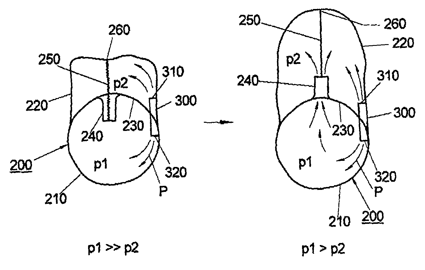
[0005]According to one embodiment of the invention, there is provided a gas bag, where the sealing off of the outflow and / or overflow orifice is achieved in that the orifice region of the gas bag envelope, i.e., the region in which the outflow and / or overflow orifice is arranged in the gas bag envelope, is drawn, that is to say slipped, into the gas bag envelope completely. The orifice is then sealed off in that the slipped-in envelope material is pressed together by the internal pressure of the gas bag, with the result that a virtually complete sealing off of the outflow and / or overflow orifice is achieved.
[0006]A particular advantage of the gas bag according to aspects of the invention, or of the sealing off according to aspects of the invention, is that the gas bag can be produced very cost-effectively, because there is no need for additional closing elements, such as are present, for example, in the previously known gas bag described in the above mentioned German laid-open publication 196 40 322 A1. By additional closing elements being dispensed with, the reliability of the gas bag according to one aspect of the invention is at the same time also increased; this is because each additional element, due to the ever-present risk of its failure, necessarily increases the risk of a technical defect.
[0008]Additionally or alternatively, an outflow and / or overflow orifice may also be formed on the outer gas bag envelope, i.e., on the outer wall of the gas bag, so that, with the outflow and / or overflow orifice open, the gas emerges from the gas bag. In this case, the outflow and / or overflow orifice acts as a straightforward “outflow orifice.” Such an outflow orifice may be provided, for example, in order to reduce the risk of injury in the event of “out of position” accidents.
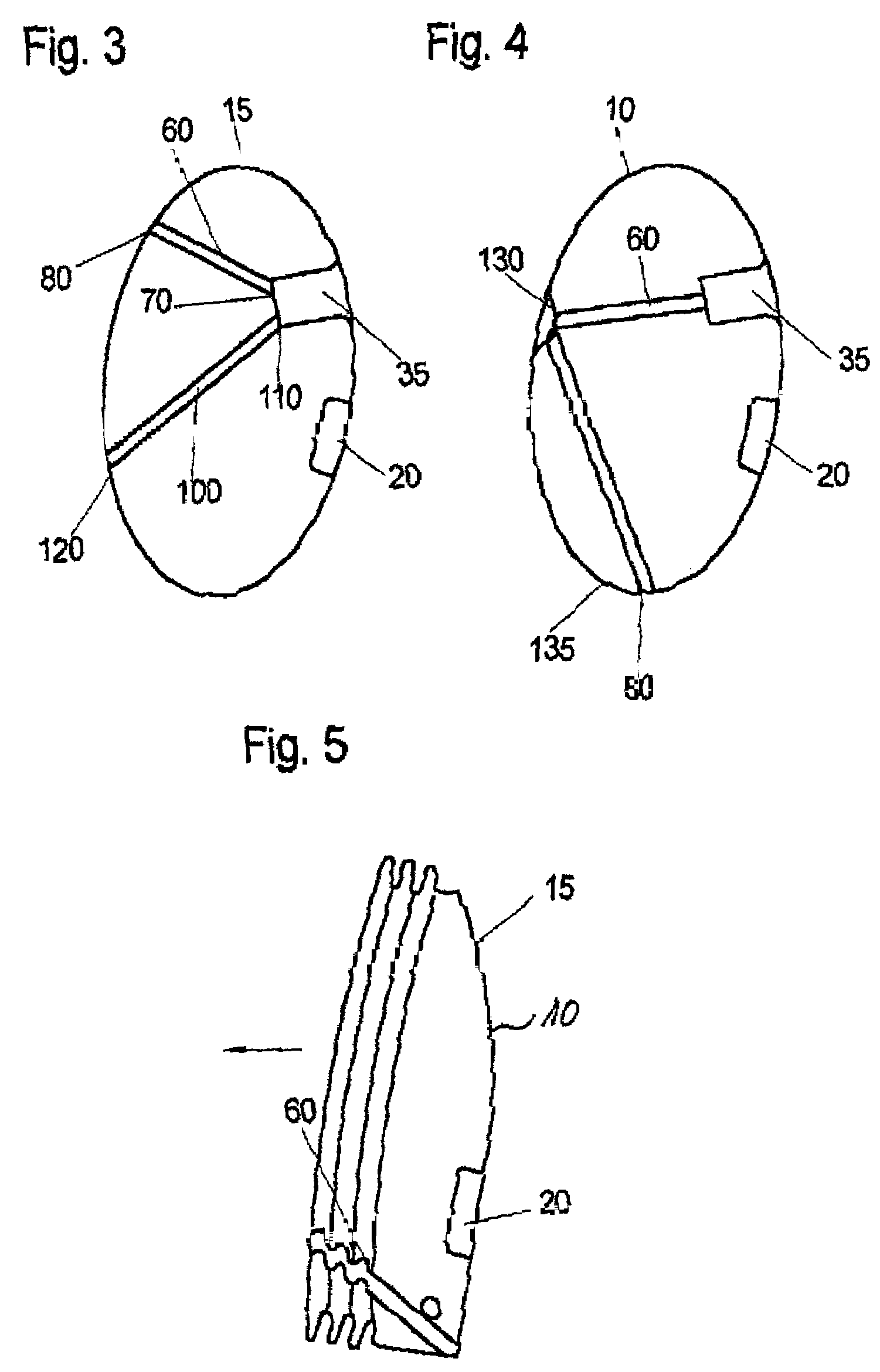
[0013]According to another aspect of the invention, it is advantageous if at least two control bands are used, which are attached at opposite points of the outflow and / or overflow orifice. This is so because in this aspect of the gas bag, the slipped-in gas bag material is drawn apart, with the result that crumpling of the slipped-in gas bag material is avoided and particularly gas-tight sealing off by means of the internal pressure of the gas bag is achieved.
[0014]According to another aspect of the invention, virtually complete sealing off of the outflow and / or overflow orifice is achieved in an advantageous way in that the orifice is hose-shaped or blowpipe-shaped, because the slipped-in gas bag material can then be pressed together ideally by virtue of its shape, optimal sealing off thereby being achieved.
[0017]The overflow orifice is preferably closed in the first inflation stage, so that the pelvic part gas bag can be inflated very quickly. As a result of the rapid pressure build-up, the vehicle occupant is pushed very quickly out of the intrusion region in the event of a side impact. After the pelvic part gas bag has performed this task, a particularly high gas pressure in the pelvic part gas bag is no longer necessary, so that the overflow orifice can be opened by means of the control band and the high gas pressure of the pelvic part gas bag can also be utilized for inflating the thoracic part gas bag. The thoracic part gas bag is thus inflated with a slight time delay. After the inflation of the thoracic part gas bag, the latter can intercept the vehicle occupant and protect him against impact on the lateral structure of the motor vehicle.

Problems solved by technology

By additional closing elements being dispensed with, the reliability of the gas bag according to one aspect of the invention is at the same time also increased; this is because each additional element, due to the ever-present risk of its failure, necessarily increases the risk of a technical defect.

Method used


Image

  • Gas bag for an airbag module
  • Gas bag for an airbag module
  • Gas bag for an airbag module

Examples


Embodiment Construction

[0026]Elements which are present in various exemplary embodiments bear the same reference symbols in each case in the corresponding figures.

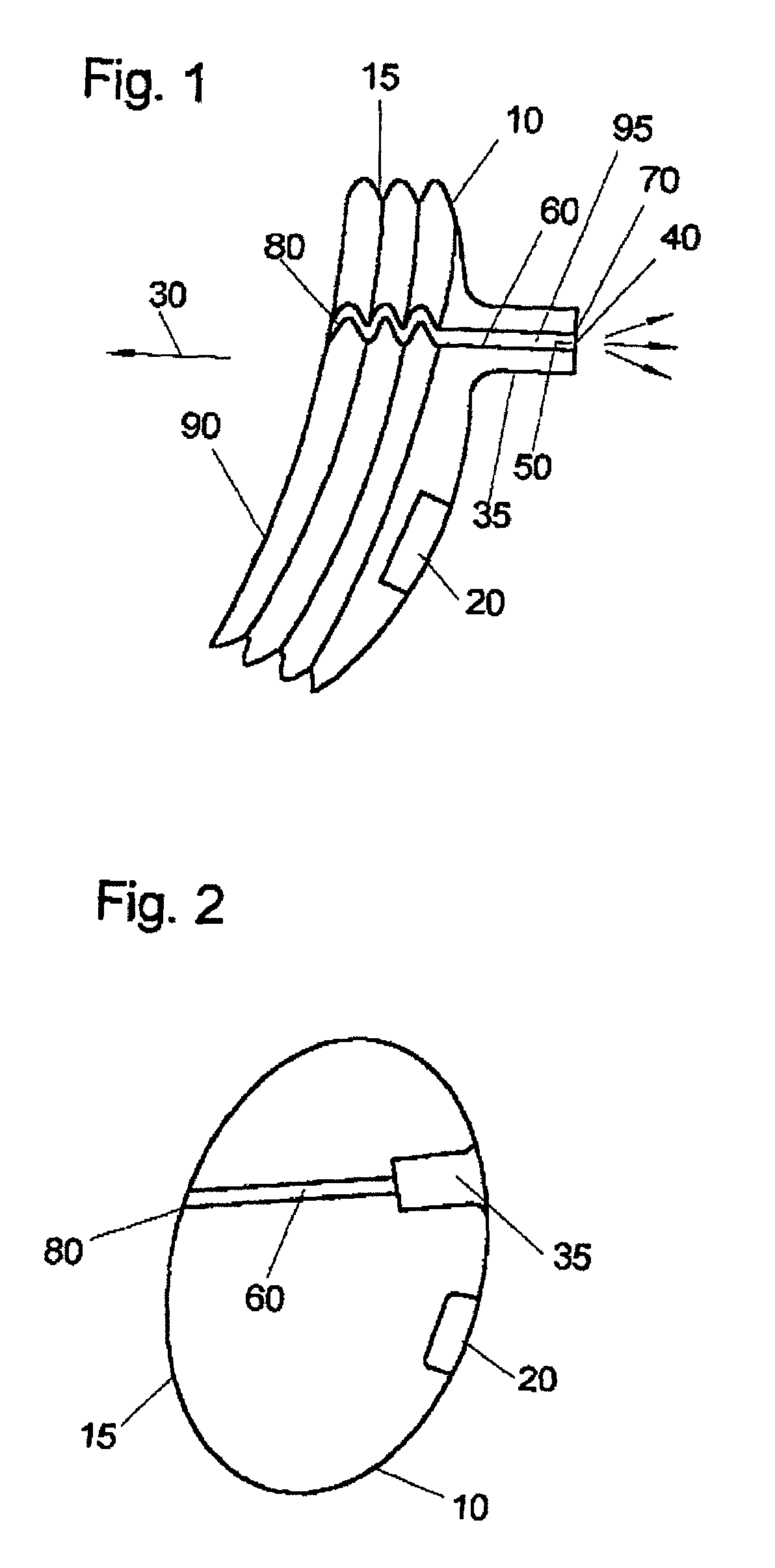
[0027]FIG. 1 illustrates a gas bag 10 with a not yet fully deployed gas bag envelope 15 which is inflated by a gas generator 20. The direction of deployment is illustrated by an arrow 30 in FIG. 1.

[0028]The gas bag 10 may have a hose-shaped or hose pipe-shaped, for example, envelope region 35 with an orifice 40, through which a gas delivered by a gas generator 20 can flow out of the gas bag 10, where the orifice 40 is designated as an outflow orifice.

[0029]In the region 50 of the outflow orifice 40, a control band 60 is fastened at one end 70. The other end 80 of the control band 60 is connected to the front region 90 of the gas bag 10. The front region 90 faces the vehicle occupant (not illustrated in FIG. 1) when arranged in the vehicle.

[0030]In FIG. 1, the outflow orifice 40 is open, so that gas delivered by the gas generator 20 can leave the...


PUM


Abstract

A gas bag in which an orifice is opened or closed with the aid of a control band as soon as the gas bag has reached a predetermined state of deployment. One end of the control band is fastened to a gas bag envelope in the region of the orifice. The control band is connected at its other end to the gas bag envelope so that, when the predetermined state of deployment is reached, the control band slips into the gas bag envelope so that the orifice is closed by the slipped-in region of the gas bag envelope by the internal pressure of the gas bag, or the control band slips out of the gas bag envelope so that the previously closed orifice is opened.

Description

BACKGROUND[0001]The invention relates to a gas bag for protecting a vehicle occupant in the event of an accident.[0002]German laid-open publication 196 40 322 A1 (incorporated by reference herein) discloses a gas bag. In this gas bag, a control band keeps an outflow orifice of the gas bag open until the gas bag has reached a predetermined state of deployment. As soon as the predetermined state of deployment is reached, the control band tears off and a closing element closes the outflow orifice of the gas bag. This gas bag has this outflow orifice, which is still open at the commencement of inflation and is closed only thereafter, arranged with a view to what are known as “out of position” situations. “Out of position” situations are those situations in which the vehicle occupant to be protected by the airbag does not assume the normal sitting position, but an abnormal sitting position, and in particular to a sitting position in which the vehicle occupant is very close to the still u...

Claims


Application Information

Patent Timeline
IPC IPC(8): B60R21/30B60R21/276B60R21/16B60R21/231B60R21/233B60R21/2338B60R21/239
CPCB60R21/233B60R21/239B60R21/2338B60R21/23138B60R2021/23382
Inventor BOSSECKER, MAXIMILIANGETZ, ROBERTSENDELBACH, HANS-PETERWEYRICH, CHRISTIANRIEDEL, ANDREAS
Owner TAKATA CORPORATION
Learn More