Vehicle bumper structure

a technology for bumpers and vehicles, applied in the direction of bumpers, vehicle components, vehicular safety arrangments, etc., can solve the problems of high cost of repairing an extension member when it has been deformed by a low-speed collision, and the airbag cannot be operated in optimal conditions, so as to reduce the cost of repair when there is a low-speed collision, the effect of speed dependency on the side members of loads

Inactive Publication Date: 2006-06-13
TOYOTA JIDOSHA KK
View PDF25 Cites 25 Cited by
  • Summary
  • Abstract
  • Description
  • Claims
  • Application Information

AI Technical Summary

Benefits of technology

[0007]In consideration of the circumstances described above, provision of a vehicle bumper structure which assures speed dependency of a load that is generated in a side member at a time of frontal collision and which can reduce costs of repair when there is a low-speed collision is required.
[0010]Hence, when the bumper cover frontally collides with a colliding body, a load is transmitted from the bumper cover through the bumper absorber to the bumper reinforcement, and is further transmitted to the side members. At this time, the collision load can be transmitted through the bumper reinforcement to the side members, directly after the collision, by the plurality of protrusion portions which are provided standing from the region of the bumper absorber that opposes the bumper reinforcement. Further, the protrusion portions at a vehicle width direction central portion of the bumper absorber, which protrude in a vehicle forward direction more than the protrusion portions at vehicle width direction outer side regions, are subjected to pressure sooner and, because of the grooves that are formed at the base portion outer peripheries of the protrusion portions, the protrusion portions consistently deform without affecting surrounding regions. As a result, a concentration of the load that is generated at the time of frontal collision at the vehicle width direction central portion of the bumper is prevented. Consequently, the generation of left-right direction loads at the front ends of the left and right side members can be prevented, and thus the speed dependency of loads that are generated in the left and right side members at times of frontal collisions is excellent. Furthermore, because the concentration of a load that is generated at a time of frontal collision at the vehicle width direction central portion of the bumper absorber can be prevented, deformation of the vehicle width direction central portion of the bumper reinforcement toward a vehicle length direction inner side at a time of low-speed collision can be prevented. Consequently, costs of repair when there is a low-speed collision can be reduced.
[0013]A vehicle bumper structure of the present invention includes: the bumper reinforcement extending in the vehicle width direction, which spans between the front ends of the left and right side members which extend in the vehicle front-rear direction; the bumper absorber, which is disposed between the bumper reinforcement and the bumper cover; the plurality of protrusion portions disposed at the region of the bumper absorber that opposes the bumper reinforcement; and the grooves which are formed at the outer peripheries of the base portions of the protrusion portions of the bumper absorber. Consequently, the vehicle bumper structure has excellent effects in that the speed dependency at the side members of loads generated at times of frontal collisions is excellent, and in that the cost of repair when there is a low-speed collision can be reduced.
[0014]When, in the vehicle bumper structure of the present invention, the peak portions of the protrusion portions include the hole portions, the region of the bumper absorber that opposes the bumper cover includes the plurality of recess portions, and the holes and the recess portions are on coincident axes in the vehicle front-rear direction, the vehicle bumper structure has an excellent effect in that control of applied loads can be implemented consistently.

Problems solved by technology

However, with this vehicle bumper structure, when there is a frontal collision, a load that is generated is concentrated at a vehicle width direction central portion of the bumper reinforcement, and buckles the bumper reinforcement toward the rear of the vehicle.
Therefore, if an acceleration sensor for operation of an airbag is provided at a rear end of a side member, that airbag cannot be operated in optimum conditions.
Furthermore, because the extension member is made of metal, costs for repairing an extension member when it has been deformed by a low-speed collision are high.

Method used


Image

  • Vehicle bumper structure
  • Vehicle bumper structure
  • Vehicle bumper structure

Examples


Embodiment Construction

[0021]An embodiment of the vehicle bumper structure of the present invention will be described in accordance with FIGS. 1 to 3.

[0022]Here, the arrow FR in the drawings indicates a vehicle forward direction, the arrow UP indicates a vehicle upward direction, and the arrow IN indicates a vehicle inner side direction.

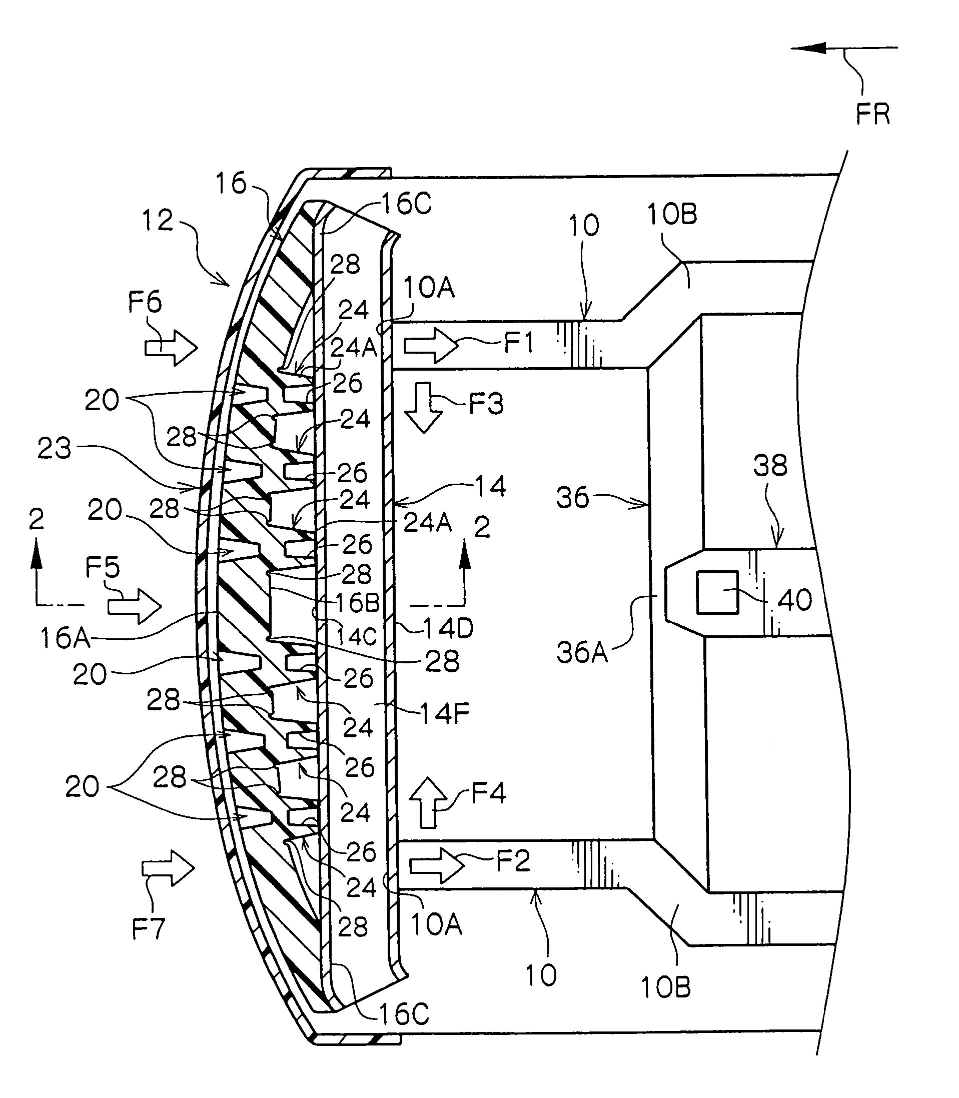
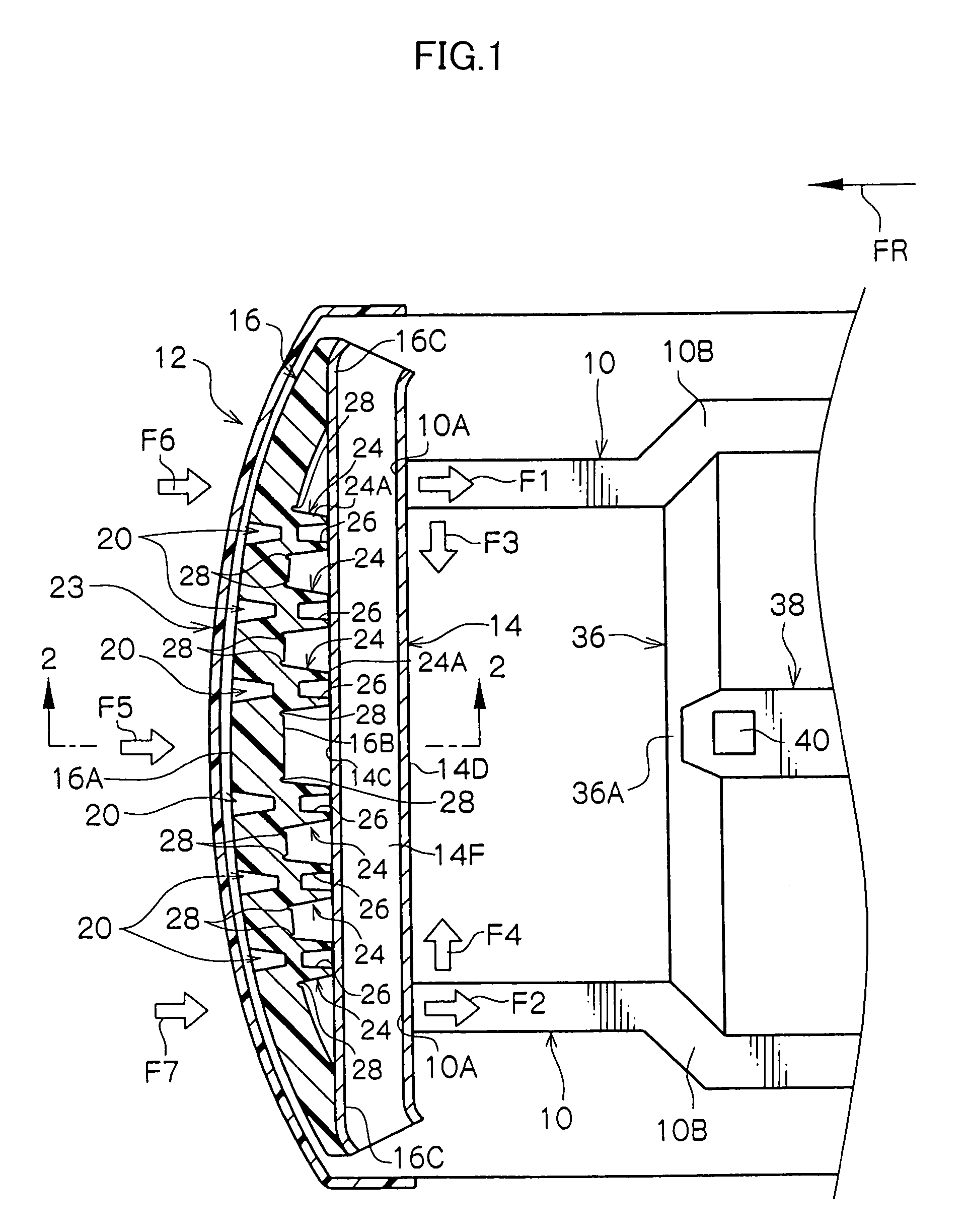
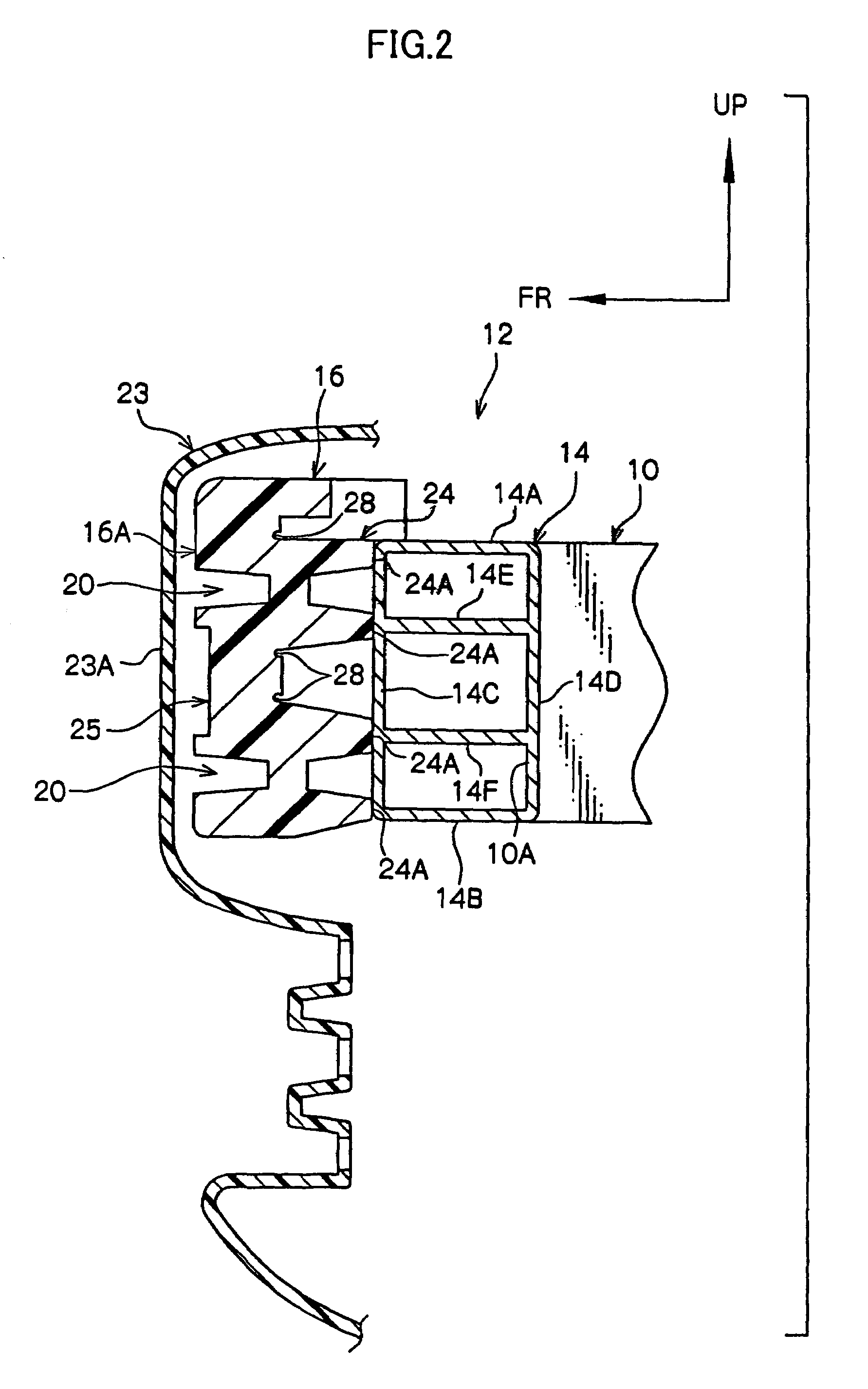
[0023]As shown in FIG. 1, a front bumper 12 is provided with a bumper cover 23 (a vehicle lateral direction member). A bumper absorber 16 (a first member at an inner side of the vehicle lateral direction member) is at an inner side of the bumper cover 23. A bumper reinforcement 14 (a second member at an inner side of the first member) is provided extending in a substantially linear form along a width direction of the vehicle. In the present embodiment, the bumper reinforcement 14 of the front bumper 12 is provided to span between front ends 10A of left and right front side members 10 (i.e., at least one pair of side members attached to the second member and running along a...


PUM


Abstract

An impact-absorbing system and method which assures speed dependency of loads generated in side members at times of frontal collisions, and reduces repair costs at times of low-speed collisions. A reinforcing member spans along a vehicle width direction in a substantially linear form between front ends of a pair of side members. A region of a rear wall portion of an impact-absorbing member, which region is disposed so as to connect between end portions of the side members, is provided with a plurality of protrusion portions which are spaced by a predetermined interval in the vehicle width direction, and includes grooves at outer peripheries of base portions of the protrusion portions. Peak portions of the protrusion portions include hole portions along a length axis of the vehicle.

Description

CROSS-REFERENCE TO RELATED APPLICATION[0001]This application claims priority under 35 USC 119 from Japanese Patent Application No. 2003-283602, the disclosure of which is incorporated by reference herein.BACKGROUND OF THE INVENTION[0002]1. Field of the Invention[0003]The present invention relates to a vehicle bumper structure, and particularly relates to a vehicle bumper structure for an automobile or the like which is provided with an energy-absorbing member.[0004]2. Description of the Related Art[0005]Secondary structures at bumper structures of vehicles such as automobiles and the like have been known heretofore. There is a structure in which left and right side members extend in a front-rear direction of a vehicle, a bumper reinforcement which extends in a vehicle width direction spans between front ends of the left and right side members, a bumper cover is provided forward of this bumper reinforcement, and an extension member is fixed at a front wall of the bumper reinforcement...

Claims


Application Information

Patent Timeline
Patent Type & Authority Patents(United States)
IPC IPC(8): B60R19/18B60R19/22
CPCB60R19/18B60R2019/186B60R2019/1806
Inventor OHNO, YOSHIKAZUNAGAE, AKIYOSHIITOH, TAKAO
Owner TOYOTA JIDOSHA KK
Why Eureka
Try Eureka