Liquid crystal display device

a liquid crystal display and display device technology, applied in the direction of printers, identification means, instruments, etc., can solve the problems of weaker rigidity of thinner parts, more deformation, uneven luminance of lcd devices, etc., and achieve uniform pressure and temperature

Inactive Publication Date: 2006-06-13
SHARP KK
View PDF5 Cites 108 Cited by
  • Summary
  • Abstract
  • Description
  • Claims
  • Application Information

AI Technical Summary

Benefits of technology

[0009]An object of the present invention is to provide a liquid crystal display device with a backlight disposed direct behind a LCD panel, which can communicate inside chambers with each other to prevent the deformation of a light diffusion plate and an optical sheet.
[0017]The LCD device with a backlight disposed direct behind a LCD panel is partitioned by a light diffusion plate and / or optical sheet into a lamp chamber and a LCD panel chamber both of which communicate with each other through vents provided in the partition, thereby eliminating the possibility of occurrence of a differential pressure between two chambers, which may cause the deformation of the light diffusion plate and / or optical sheet.
[0018]The LCD device according to the present invention can achieve a uniform pressure and temperature inside and outside of the device by communicating the lamp chamber and the LCD panel chamber to the ambient air.

Problems solved by technology

However, the thinner parts may be weaker in rigidity and more deformable.
In consequence of this, the LCD device becomes to have luminance unevenness.
However, this method does not consider the effect of differential pressure produced between the front chamber and the rear chamber partitioned by the light diffusion plate.

Method used


Image

  • Liquid crystal display device
  • Liquid crystal display device
  • Liquid crystal display device

Examples


Embodiment Construction

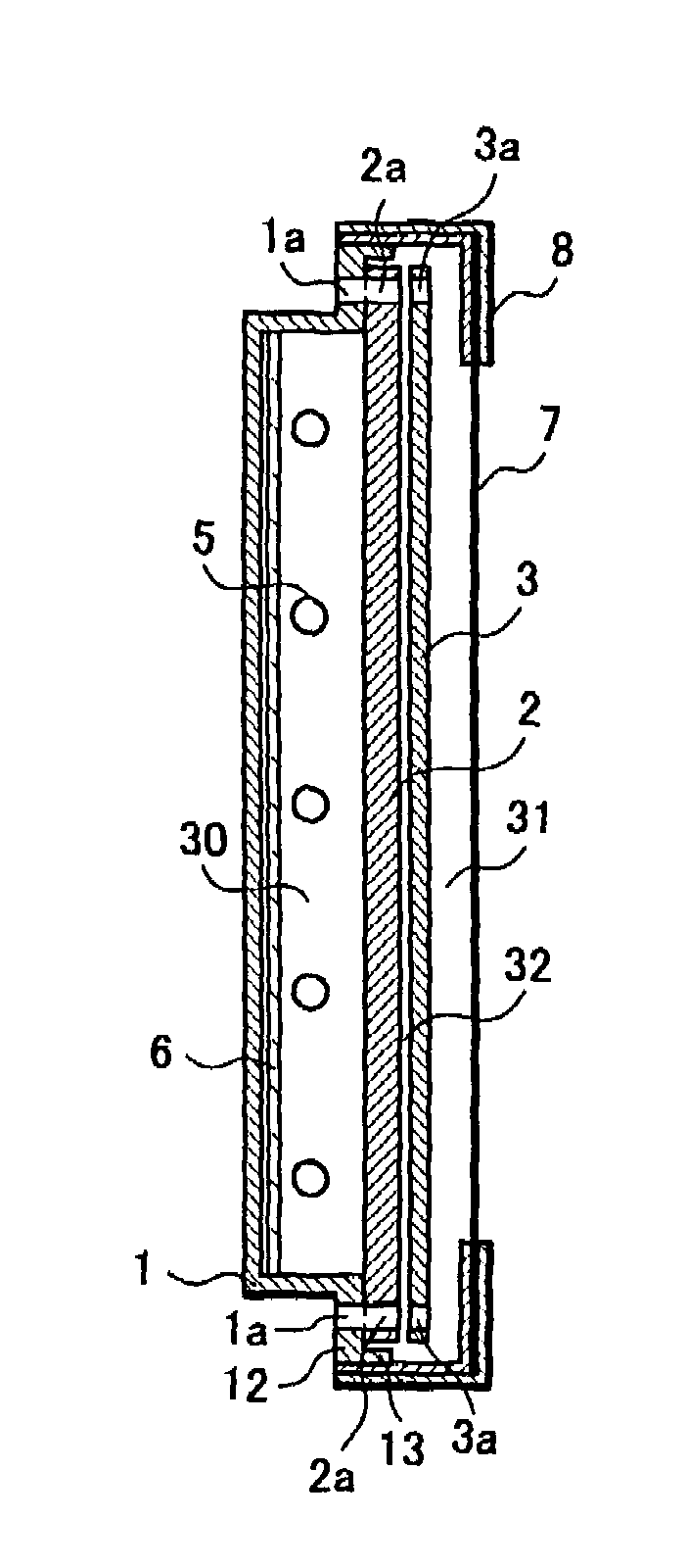
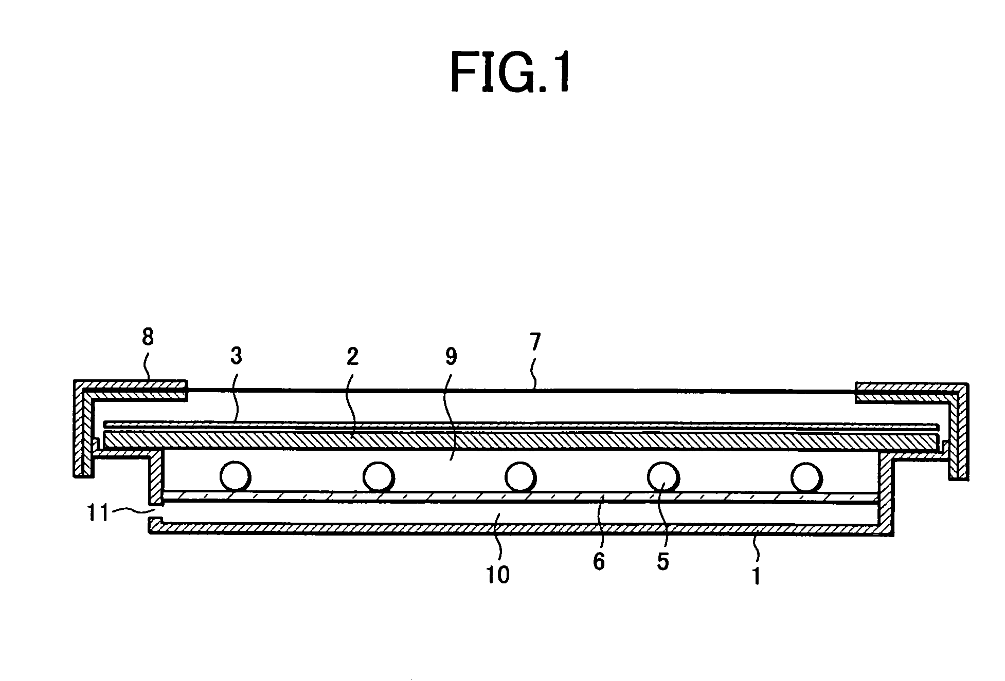
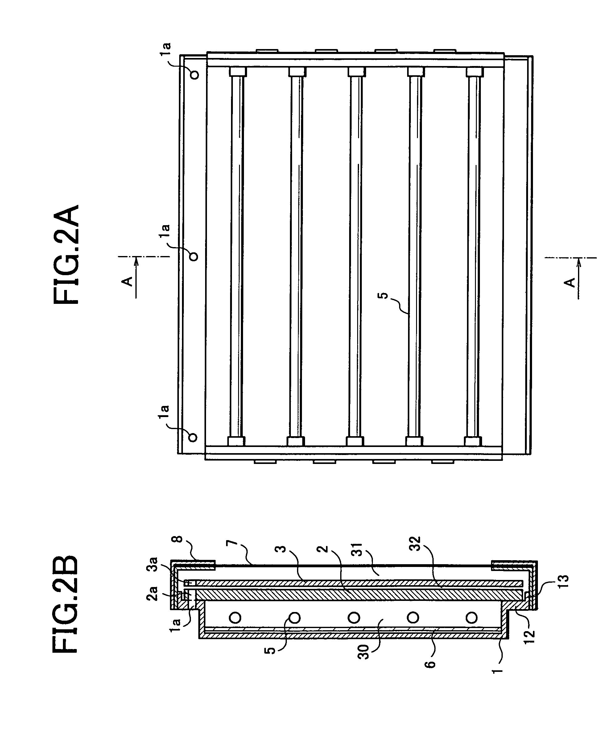
[0027]First, we will explain a history and technical background which led us to make the present invention. In the art of producing LCD devices including backlights, it has been commonly believed that the LCD devices must be designed to have airtight construction preventing the penetration of dust and dirt. The conventional LCD devices have been relatively small display panel provided with a relatively small light diffusion plate having a relatively small elongation by the effect of heat from the lamps, so the deflection and wrinkling of the light diffusion plate is negligible and does not cause a considerable unevenness of brightness of the LCD panel. Recently, there has been a rising demand for LCD devices having a larger display panel and a thinner thickness, which requires the use of a light diffusion plate having a larger working surface and thinner in depth size. On the other hand, the light diffusion plate having a large surface and thin depth has reduced rigidity and may con...


PUM

PropertyMeasurementUnit
timeaaaaaaaaaa
heat radiating propertyaaaaaaaaaa
temperatureaaaaaaaaaa

Abstract

A liquid crystal display device has a plurality of lamps, a light diffusion plate and / or an optical sheet, a shield portion for accommodating the lamps, the light diffusion plate and / or the optical sheet. There is a liquid crystal display panel located opposite to one side of the light diffusion plate and / or the optical sheet opposed each with the other side to the lamps. The light diffusion plate and / or the optical sheet each have a vent, and a lamp chamber formed in the lamp-accommodating side of the light diffusion plate and / or the optical sheet. There is an LCD panel chamber formed in the LCD panel-disposing side of the light diffusion plate and / or an optical sheet that communicate with each other through the vent of the light diffusion plate and / or optical sheet.

Description

FIELD OF THE INVENTION[0001]The present invention relates to a liquid crystal display device and more specifically to a technical method for preventing the deformation of a light diffusion plate and an optical sheet disposed ahead of backlight lamps.BACKGROUND OF THE INVENTION[0002]Japanese Laid-open Patent Publication No. H10-106315 discloses a conventional technical method for improving heat radiating property of a liquid crystal display device. The method disclosed in the above document is such that the LCD device body is partitioned by a reflecting plate into two chambers disposed one on the LCD panel side and one behind the reflecting plate. The LCD panel side chamber is embodied in a tightly closed structure so as to prevent penetration of dust from the outside and the backside chamber has vents through which the ambient air is introduced to flow along the one side surface of the reflecting plate to cool down the front chamber.[0003]FIG. 1 is a construction view of a conventio...

Claims


Application Information

Patent Timeline
Patent Type & Authority Patents(United States)
IPC IPC(8): A47F3/00F21V7/04H03H9/00G02F1/1333G02F1/13G02F1/1335G02F1/13357G09F9/00G09F9/35
CPCG02F1/133308G02F1/133604G09F19/228G02F2001/133628G02F2201/36G02F1/133606G02F1/133628G02F1/1335
Inventor SHIMIZU, MASAKI
Owner SHARP KK
Why Eureka
Try Eureka