Elastic fastener

a technology of elastic fasteners and fasteners, applied in the direction of fastening means, screws, dowels, etc., can solve the problems of insufficient recycling, long forming time, low ozone resistance, etc., and achieve the effects of reducing forming time, enhancing ozone resistance, and reducing weight of elastic fasteners

Inactive Publication Date: 2006-06-13
NEWFREY
View PDF11 Cites 36 Cited by
  • Summary
  • Abstract
  • Description
  • Claims
  • Application Information

AI Technical Summary

Benefits of technology

[0008]As above, the tubular portion and the flange are formed of the specific elastomeric material, and the internally threaded portion is formed of the specific rigid resin material (high-strength engineering plastic) without using any metal nut. Thus, an overall weight reduction of the elastic fastener can be sufficiently achieved (one-half or less of the weight of the conventional elastic fastener), and the availability of fusion bonding for joining the internally threaded portion to the tubular portion allows the need for adhesive to be eliminated. The tubular portion and the flange formed of the above materials can also achieve significantly reduced forming time (one-third or less of the forming time of the conventional elastic fastener) and enhanced ozone resistance, as compared to those formed of a chloroprene rubber. Further, it has been proved that the elastic fastener of the present invention was improved in vibration resistance.

Problems solved by technology

Thus, the elastic fastener still is involved with a challenge to be improved in terms of weight reduction, and is not adequate to recycle because it mixedly includes metal and rubber.
In addition, the chloroprene rubber as a material of the tubular portion and flange leads to long forming time and low ozone resistance.

Method used


Image

  • Elastic fastener
  • Elastic fastener
  • Elastic fastener

Examples


Embodiment Construction

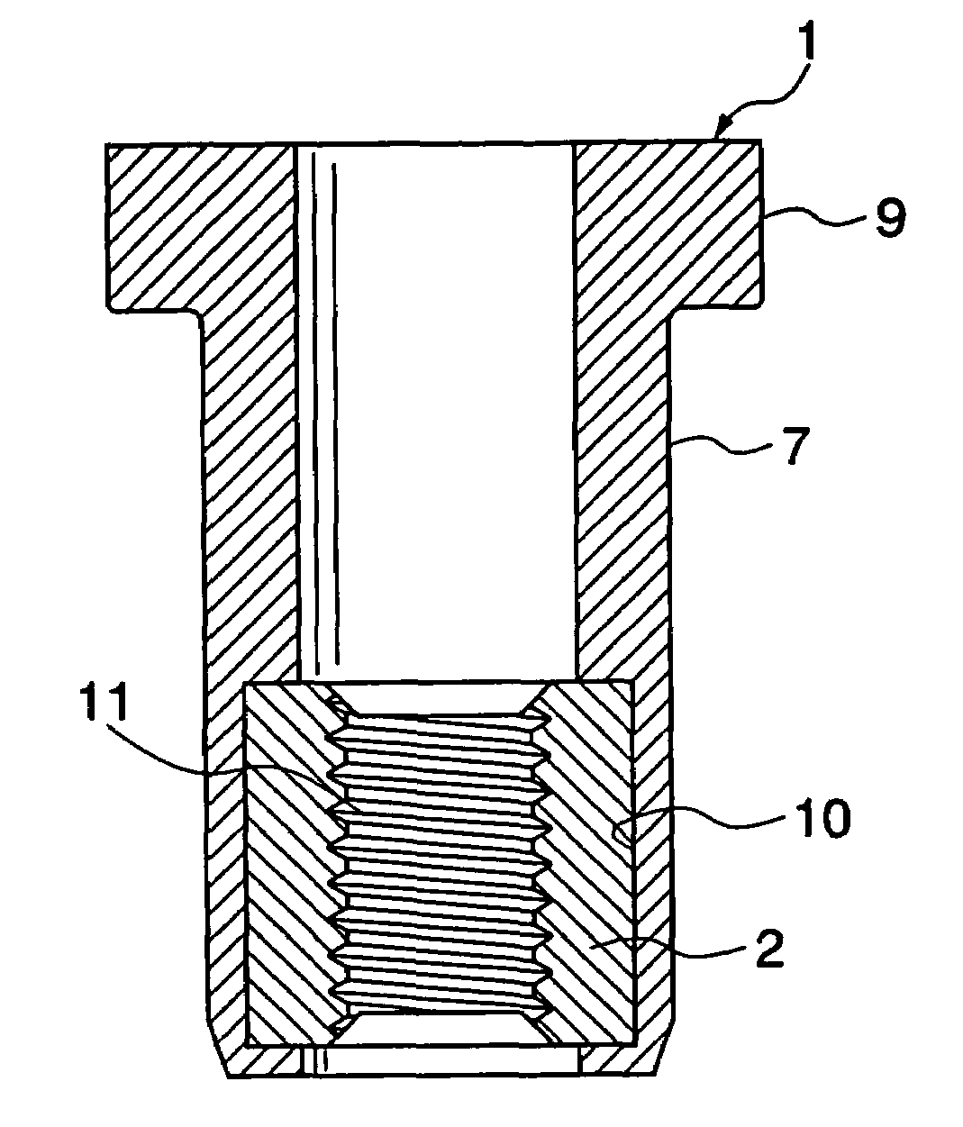
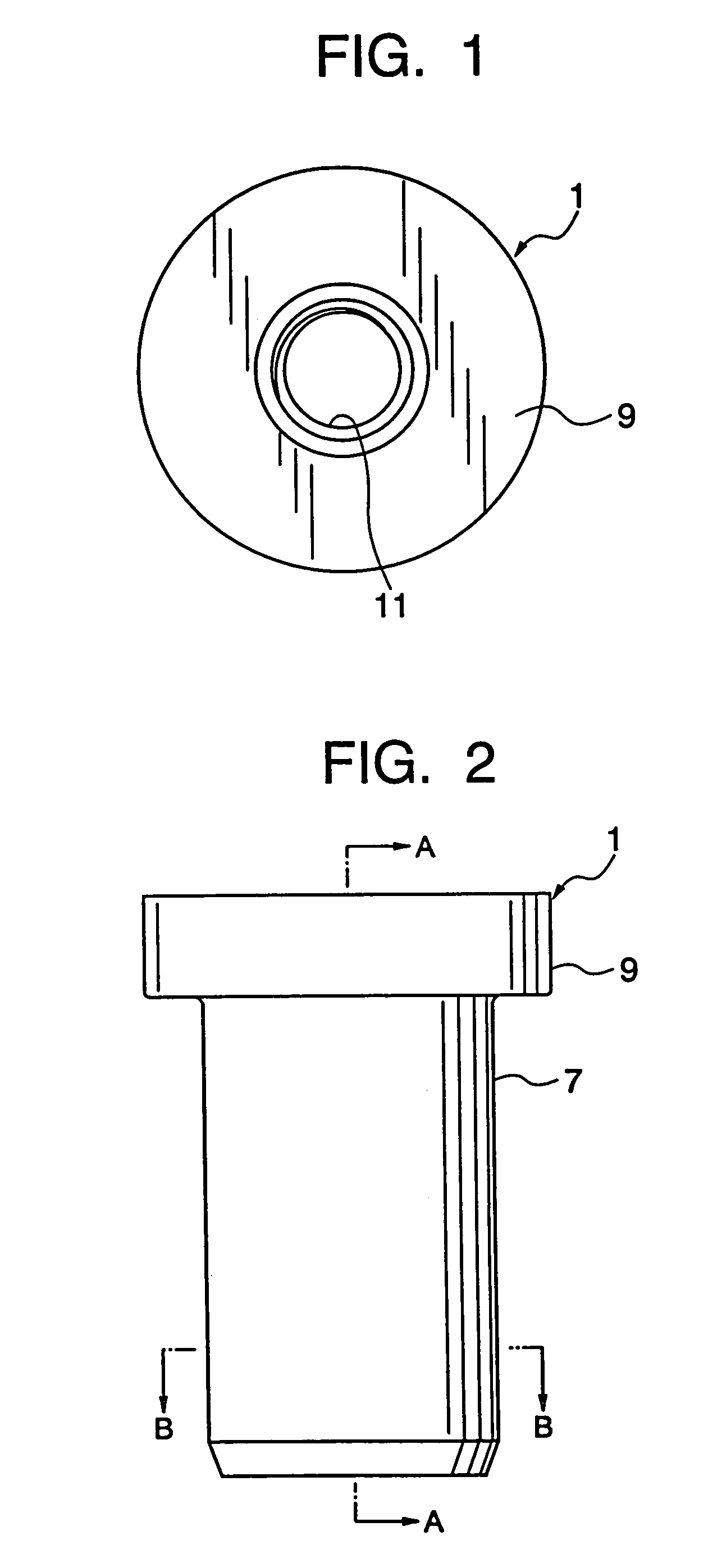
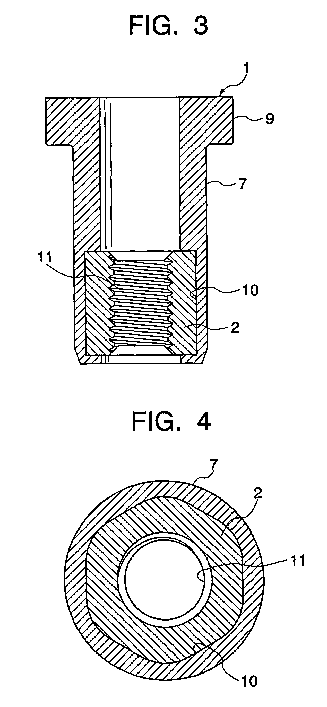
[0018]With reference to the drawings, an embodiment of the present invention will now be described. FIGS. 1 to 4 show a blind nut type elastic fastener 1 according to the present invention. FIGS. 5 and 6 show an internally threaded portion 2 of the elastic fastener 1. FIG. 7 shows the condition that the elastic fastener 1 is fixed to a workpiece 3 such as a vehicle body by screwing a headed bolt 5 into the elastic fastener, and an attachment member 6 such as a bracket or an attachment panel is fixed to the fastener 1 with the bolt 5

[0019]In FIGS. 1 to 4, the elastic fastener 1 comprises a hollow cylindrical portion 7, an internally threaded portion 2 provided at one (lower end) of the ends of the tubular portion 7, and a circular flange 9 formed at the other end (upper end) of the tubular portion. The tubular portion 7 and the flange 9 are not limited to be a round shape, and may be a square or polygonal shape. The tubular portion 7 and the flange 9 are integrally formed with each o...


PUM


Abstract

An elastic fastener 1 comprises a hollow tubular portion 7, an internally threaded portion 2 provided at one of the ends of the tubular portion 7, and a flange 9 formed at the other end of the tubular portion 7. The tubular portion 7 and the flange 9 are integrally formed of an elastomeric material, such as a styrene-based elastomer, a polyamide-based elastomer and a polyester-based elastomer. The internally threaded portion 2 is formed of a rigid resin material such as a polycarbonate resin. The internally threaded portion 2 is integrally fixed to the tubular portion 7 in a hole of the tubular portion.

Description

CROSS REFERENCE TO OTHER APPLICATIONS[0001]The present application is a continuation of pending International patent application PCT / US02 / 30736 filed on Sep. 27, 2002 which designates the United States, and which claims priority of Japanese 2001-308981 filed on Oct. 4, 2001.FIELD OF THE INVENTION[0002]The present invention relates to an elastic fastener usable as a blind nut and capable of being fastened to a workpiece, such as a panel, from one side thereof.BACKGROUND OF THE INVENTION[0003]There has been well known a metal blind nut comprising a hollow tubular portion, an internally threaded portion formed at one of the ends of the tubular portion and a flange formed at the other end of the tubular portion, wherein the tubular portion is adapted to be buckled or deformed by inserting the tubular portion into a hole of a workpiece so that the blind nut is fastened to the workpiece by the deformed portion and the flange (for example, Japanese Utility Model Laid-Open No. 59-146607). T...

Claims


Application Information

Patent Timeline
Patent Type & Authority Patents(United States)
IPC IPC(8): F16B13/04F16B29/00F16B33/00
CPCF16B33/006F16B29/00
Inventor ANDO, TOSHIOMASUGATA, HIROYUKI
Owner NEWFREY
Why Eureka
Try Eureka