Method and system for controlling and recovering short duration bridge power to maximize backup power

a bridge power and short-term technology, applied in the field of power systems, can solve problems such as excess power generation, extended power outages, and practical or possible turning

Inactive Publication Date: 2006-06-13
PROTON ENERGY SYST
View PDF34 Cites 63 Cited by
  • Summary
  • Abstract
  • Description
  • Claims
  • Application Information

AI Technical Summary

Problems solved by technology

Geographically remote areas such as islands or mountainous regions are often not connected to main utility electrical grids due to the cost of installing and maintaining the necessary transmission lines to carry the electricity.
Even in remote communities where the transmission lines are in place, it is not uncommon for frequent and extended power outages due to weather related faults.
In either case, to prevent economic loss in times of an electrical outage, it is often necessary for these communities or industries in these regions to create local “micro” electrical grids to ensure a reliable and uninterruptible power system.
This uninterruptible power system may be either a primary system where there is no connection to the main utility grid, or a backup system that activates when an outage occurs.
Since it is not often practical or possible to turn generation sources on and off, inevitably excess power will be generated.
As the load requirements of the grid increase, it is difficult or impossible to recapture the converted energy back into electrical energy for use in the electrical grid.
Further complicating matters is that renewable power sources do not typically run continuously at full power and will experience extended periods of low to no energy output (e.g. night time or seasonal low wind periods).
However, because regenerative fuel cell systems generally take a certain amount of time from the point of initial activation to delivering full power, there may be a brief delay of power attendant thereto when switching over from a primary power supply to backup power generated by a fuel cell supply.

Method used


Image

  • Method and system for controlling and recovering short duration bridge power to maximize backup power
  • Method and system for controlling and recovering short duration bridge power to maximize backup power
  • Method and system for controlling and recovering short duration bridge power to maximize backup power

Examples


Embodiment Construction

[0028]The following description will provide specific examples with respect to the load and power source voltages for example only. It will also be understood that the method and apparatus for bridging short duration power interruptions may be used with different types of primary / secondary sources and / or other operating voltages, and is not limited to the implementations described herein. Various power sources range from grid power to solar power, hydroelectric power, tidal power, wind power, fuel cell power, and the like, as well as combinations comprising at least one of the foregoing power sources (e.g., via solar panel(s), wind mill(s), dams with turbines, electrochemical cell systems, and the like).

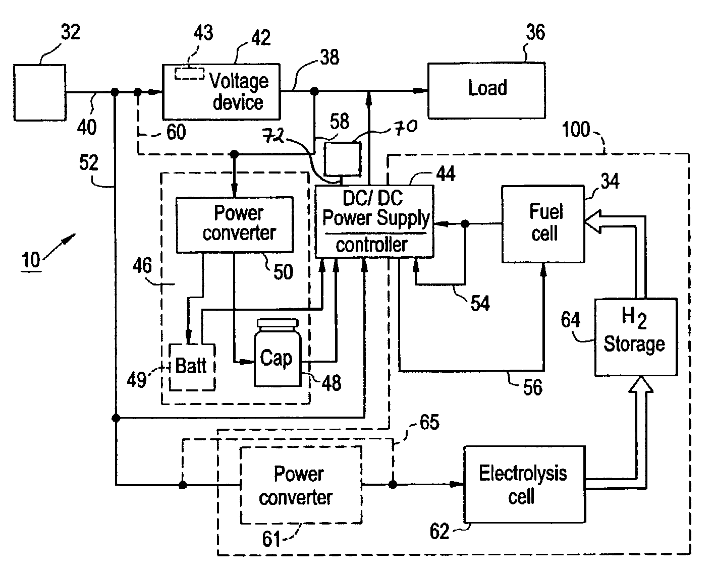
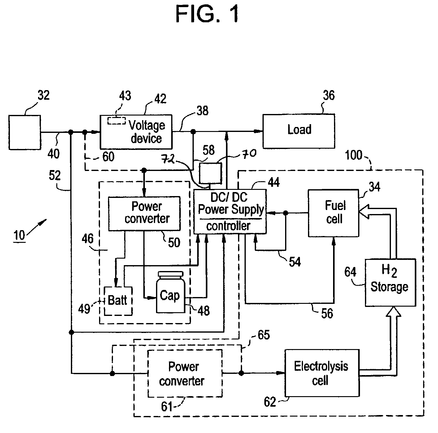
[0029]FIG. 1 depicts a block diagram of a portion of power system 10 having a primary power source 32 such as generated grid power or that from a renewable source, a secondary power source 100 and a load 36, which load 36 is fed from a feeder bus 38. In the example shown, the primary...


PUM

PropertyMeasurementUnit
capacitanceaaaaaaaaaa
voltageaaaaaaaaaa
voltageaaaaaaaaaa

Abstract

A power system, comprising: a primary power source in electrical communication with a bus and a bridging power source, wherein the bridging power source comprises at least one of a capacitor, a battery, and an electrolysis cell, and the bridging power source is in electrical communication with the bus; and a secondary power source in electrical communication with the bus. A method for operating a power system, comprising: monitoring a primary power source; if the primary power source exhibits selected characteristics, directing power from a bridging power source to a bus and initiating a secondary power source, and the bridging power source comprises at least one of a capacitor, a battery, and an electrolysis cell; and unless the secondary power source exhibits the selected characteristics, powering the bus with the secondary power source and ceasing the directing power from the bridging power source.

Description

CROSS REFERENCE TO RELATED APPLICATIONS[0001]This application claims the benefit of U.S. Provisional Application No. 60 / 328,996, filed Oct. 12, 2001 and U.S. Provisional Application No. 60 / 410,412, filed Sep. 13, 2002 the contents of which are incorporated by reference herein in their entirety.BACKGROUND OF INVENTION[0002]This disclosure relates generally to power systems, and especially relates to the storage and recovery of energy from a renewable power source and electrochemical cells.[0003]Geographically remote areas such as islands or mountainous regions are often not connected to main utility electrical grids due to the cost of installing and maintaining the necessary transmission lines to carry the electricity. Even in remote communities where the transmission lines are in place, it is not uncommon for frequent and extended power outages due to weather related faults. In either case, to prevent economic loss in times of an electrical outage, it is often necessary for these co...

Claims


Application Information

Patent Timeline
Patent Type & Authority Patents(United States)
IPC IPC(8): H01M10/46H01M8/04H01M8/00H01M8/06H01M16/00H02J3/38H02J7/34H02J9/06
CPCH01M8/04626H01M8/04656H01M8/0488H01M8/04888H01M10/465H01M16/003H02J7/345H02J9/06H01M8/04567H01M8/04208Y02B90/14H01M8/04955H01M8/0656H02J2001/004Y02E60/50Y10S429/90H02J2300/30Y02B90/10Y02E60/10
Inventor SPERANZA, A. JOHNCARDIN, MICHAELMOULTHROP, LAWRENCELILLIS, MARKZAGAJA, JOHN
Owner PROTON ENERGY SYST
Why Eureka
Try Eureka