
Cascadable current-mode regulator

a current-mode regulator and current-mode technology, applied in the direction of dc-dc conversion, power conversion system, dc source parallel operation, etc., can solve the problems of signal degradation and noise interference, other problems that cannot be solved by prior solutions, and additional components necessitate additional cost, etc., to achieve the effect of simple and low-cost devices

Inactive Publication Date: 2006-06-13
INTERSIL INC
View PDF5 Cites 34 Cited by
  • Summary
  • Abstract
  • Description
  • Claims
  • Application Information

AI Technical Summary

Benefits of technology

"The present invention relates to a cascadable power regulator that uses digital signals to communicate between channels. The regulator includes a programmable delay unit and PWM control logic that controls each PWM cycle in response to the digital input signal and an output control condition. The cascadable regulator thus uses digital signals to communicate between channels, which are not prone to signal degradation or noise susceptibility. The controller is a relatively simple, low-cost device. The multiphase power converter includes multiple regulators coupled in a cascade configuration, multiple switching circuits, and a controller. The method of controlling each regulator includes sensing the output voltage and providing a compensation signal to the regulator. The technical effects of the invention include improved efficiency, reliability, and reduced complexity of the power conversion system."

Problems solved by technology

Signal problems necessitate added expense in terms of extra components to suppress noise, layout constraints, and reduced phase count.
Other problems remain unsolved by prior solutions.
The triangle-shaped signal is an analog signal, and is therefore subject to signal degradation and noise interference.
The noise generated by one channel switching corrupts the triangle-shaped signal reaching the other channels, which limits the time separation between two channels to some value necessary to allow the noise to dissipate.

Method used


Image

  • Cascadable current-mode regulator
  • Cascadable current-mode regulator
  • Cascadable current-mode regulator

Examples


Embodiment Construction

[0018]The following description is presented to enable one of ordinary skill in the art to make and use the present invention as provided within the context of a particular application and its requirements. Various modifications to the preferred embodiment will, however, be apparent to one skilled in the art, and the general principles defined herein may be applied to other embodiments. Therefore, the present invention is not intended to be limited to the particular embodiments shown and described herein, but is to be accorded the widest scope consistent with the principles and novel features herein disclosed.

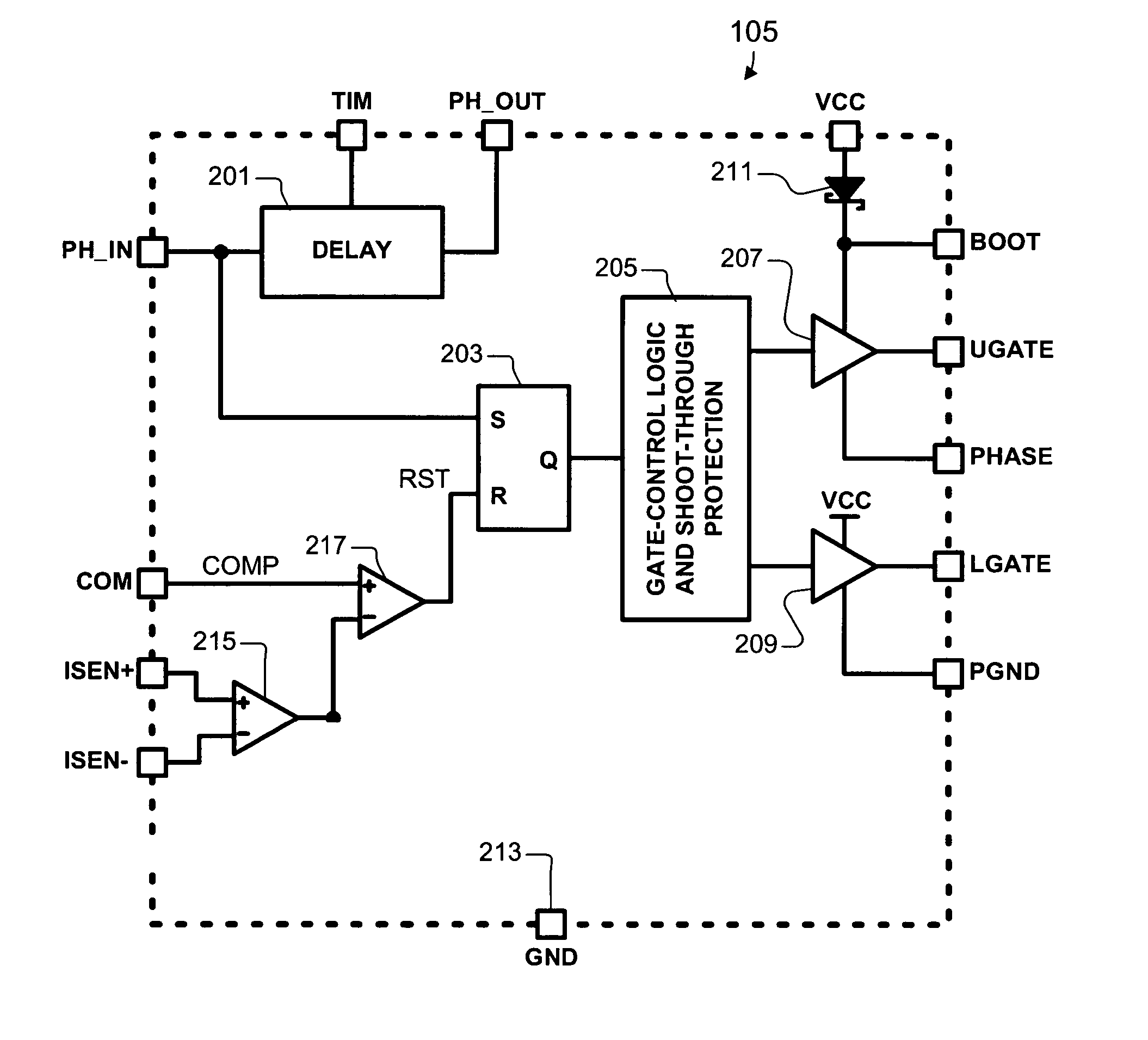
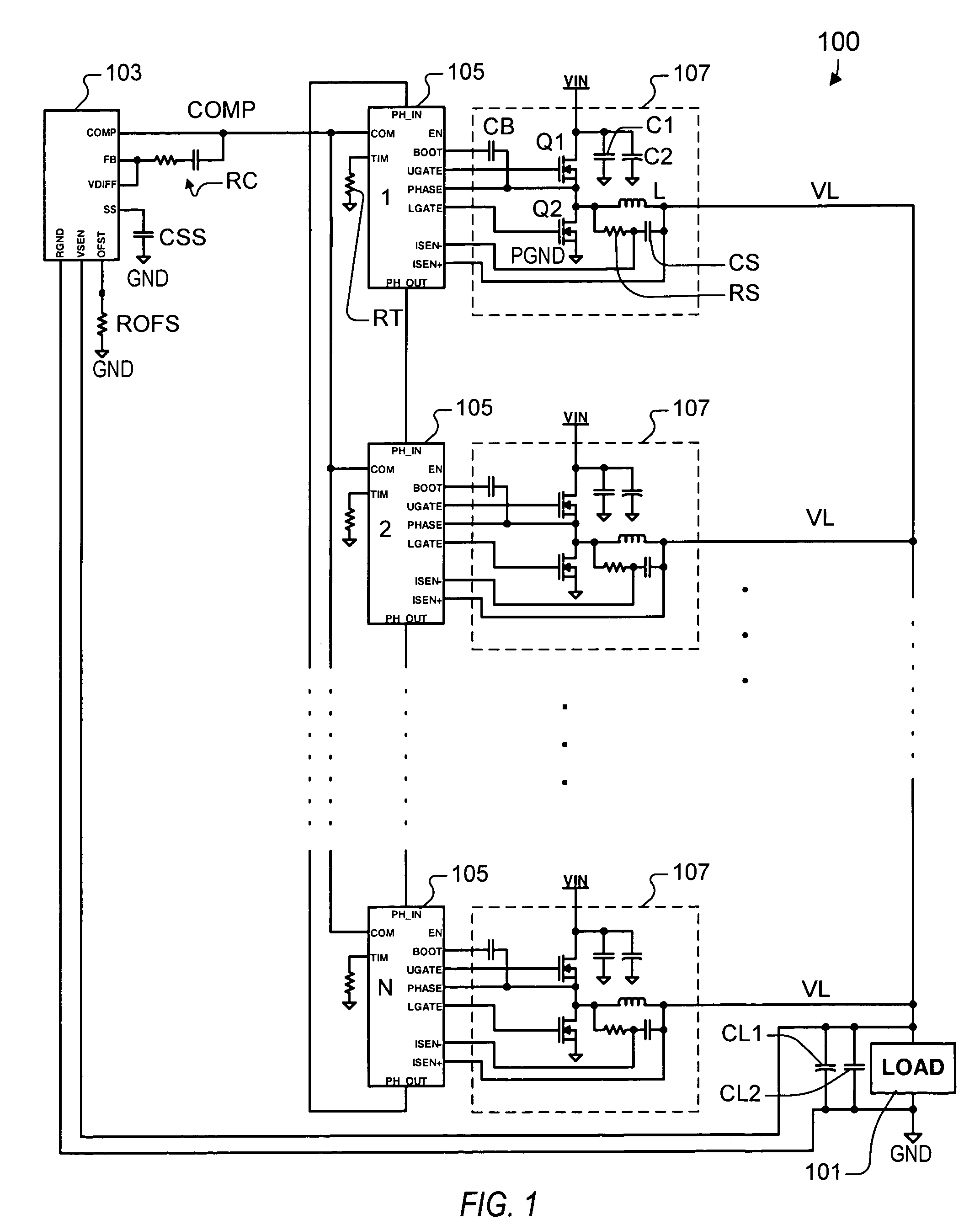
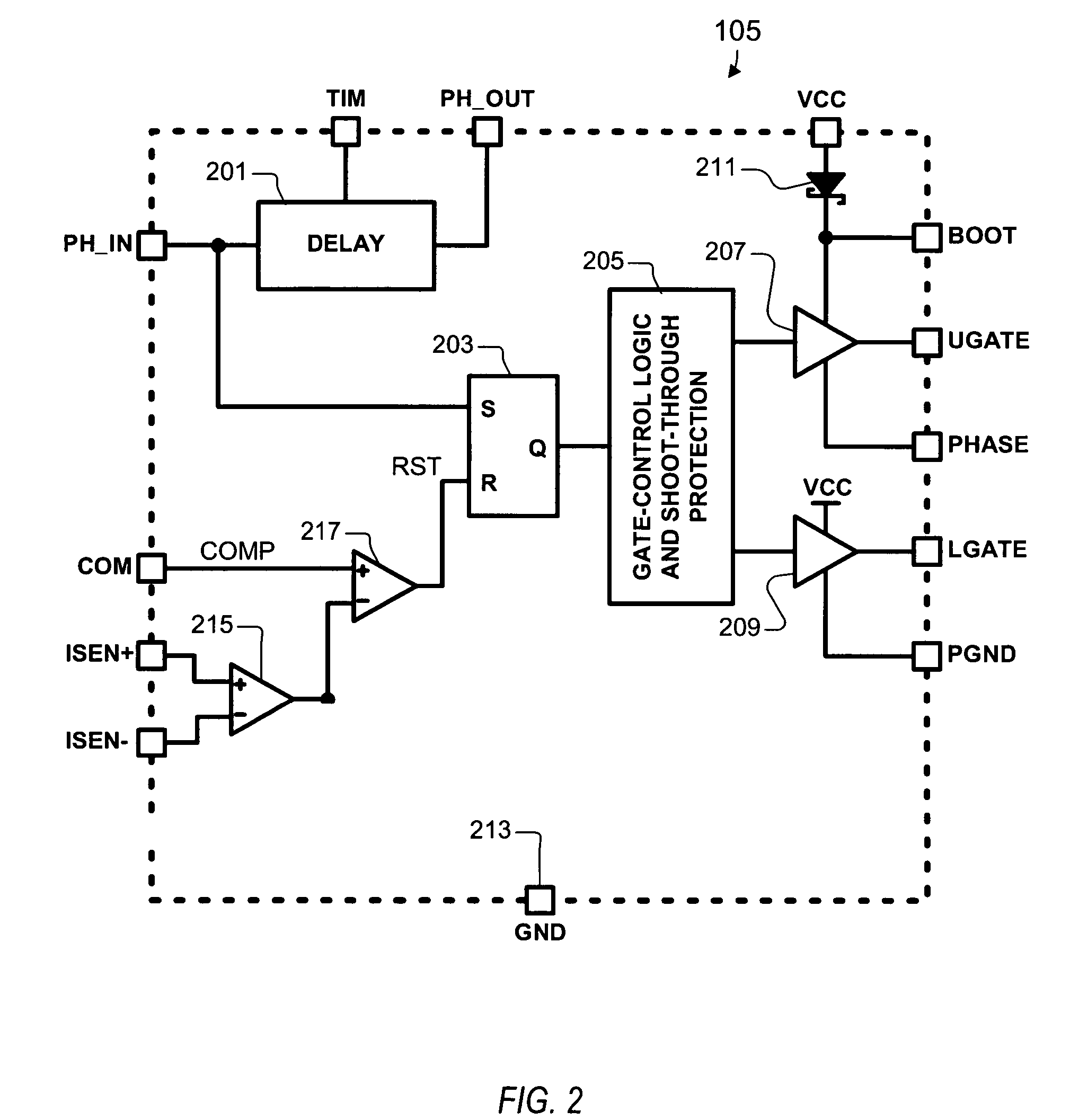
[0019]A cascadable current-mode regulator according to an embodiment of the present invention uses a digital signal to communicate between channels. The current-mode regulator may be used alone or cascaded with other similar regulators for a DC-DC converter with multiple channels. As used herein, the term “converter” is used to denote a cascaded configuration of multiple “regul...


PUM


Abstract

A cascadable power regulator including a programmable delay unit and PWM control logic. The programmable delay unit initiates a delay period in response to a digital input signal and asserts a digital output signal upon expiration of the delay period. The PWM control logic controls a PWM cycle in response to the digital input signal and in response to an output control condition. The cascadable regulator uses digital signals to communicate between channels. Digital signals are not prone to the same kind of signal degradation or noise susceptibility as analog signals. Thus, the number of phases is not limited, the physical separation between the regulators is not limited, and the switching frequency is not as limited. There is no clock signal from a separate controller so that the controller is a relatively simple, low-cost device. Since there is no clock, a unique self-oscillating system is achieved using the cascadable regulator.

Description

CROSS-REFERENCE TO RELATED APPLICATIONS[0001]This application claims the benefit of U.S. Provisional Application No. 60 / 508,106 filed on Oct. 2, 2003, which is herein incorporated by reference for all intents and purposes.BACKGROUND OF THE INVENTION[0002]1. Field of the Invention[0003]The present invention relates to PWM power regulators and / or multi-phase DC-DC converters, and more particularly to a clockless, cascading, current-mode regulator with high noise immunity and arbitrary phase count.[0004]2. Description of the Related Art[0005]Multi-phase power conversion and current-mode control are commonly used methods for DC-DC power conversion for the electronic market. Multi-phase power conversion provides a cost-effective power solution when load currents are no longer easily supported by single-phase converters. The switching of each channel is timed to be symmetrically out of phase with each of the other channels. The multi-phase approach offers cost-saving advantages with impro...

Claims


Application Information

Patent Timeline
Patent Type & Authority Patents(United States)
IPC IPC(8): G05F1/40H02J1/10H02M3/158H02M3/28
CPCH02M3/1584H02J1/102
Inventor HARRIS, MATTHEW B.
Owner INTERSIL INC
Learn More