Segmented microstrip patch antenna with exponential capacitive loading

a patch antenna and capacitive loading technology, applied in the field of patch antennas, can solve the problem that the microstrip patch antenna suffers from limited bandwidth, and achieve the effect of reducing the resonant effect of the antenna and increasing the bandwidth

Inactive Publication Date: 2006-06-13
THE UNITED STATES OF AMERICA AS REPRESENTED BY THE SECRETARY OF THE NAVY
View PDF9 Cites 12 Cited by
  • Summary
  • Abstract
  • Description
  • Claims
  • Application Information

AI Technical Summary

Benefits of technology

[0007]It is an object of the present invention to provide a new and improved microstrip patch antenna that has improved bandwidth characteristics.
[0009]It is a further object of the present invention to provide a microstrip patch antenna that has improved bandwidth characteristics for a variety of antenna applications.
[0012]The microstrip patch antenna of the present invention enhances bandwidth by reducing the resonant effects of the antenna. The microstrip patch antenna of the present invention does not have any portion or components that support a resonant mode. Thus, the primary and secondary electrically conductive segments and the feed structure do not support a resonant mode. The microstrip patch antenna of the present invention does not utilize parasitic elements and does not use capacitive coupling to connect the antenna structure to the feedline which is typically done in prior art patent antenna systems. In the microstrip patch antenna of the present invention, capacitive gaps are used to connect the individual segments into a single antenna.

Problems solved by technology

Such a microstrip patch antenna suffers from limited bandwidth as a result of its resonant properties.

Method used


Image

  • Segmented microstrip patch antenna with exponential capacitive loading
  • Segmented microstrip patch antenna with exponential capacitive loading
  • Segmented microstrip patch antenna with exponential capacitive loading

Examples


Embodiment Construction

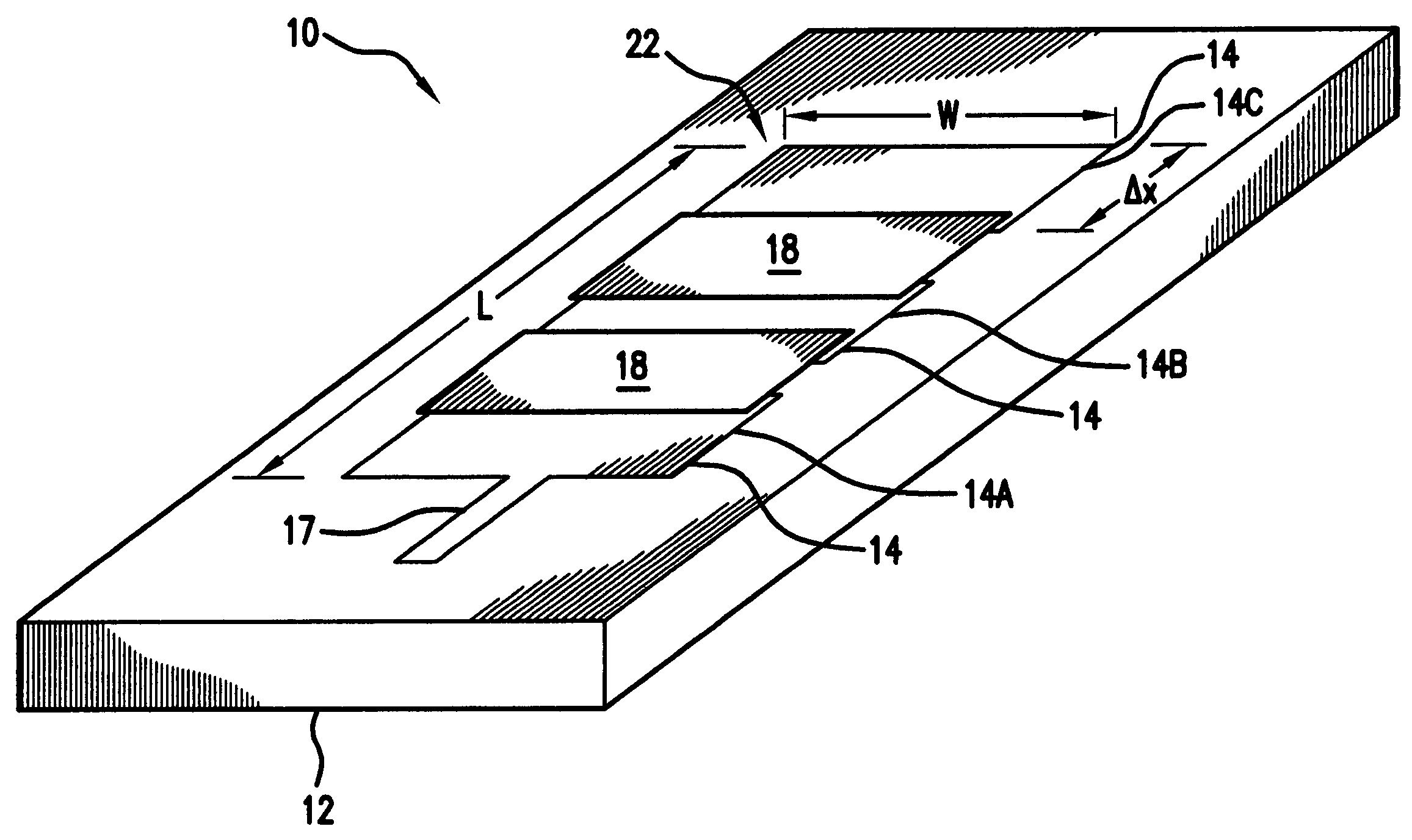
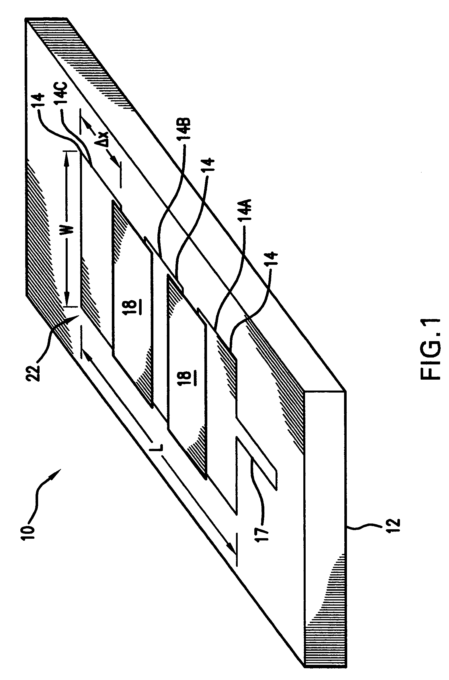
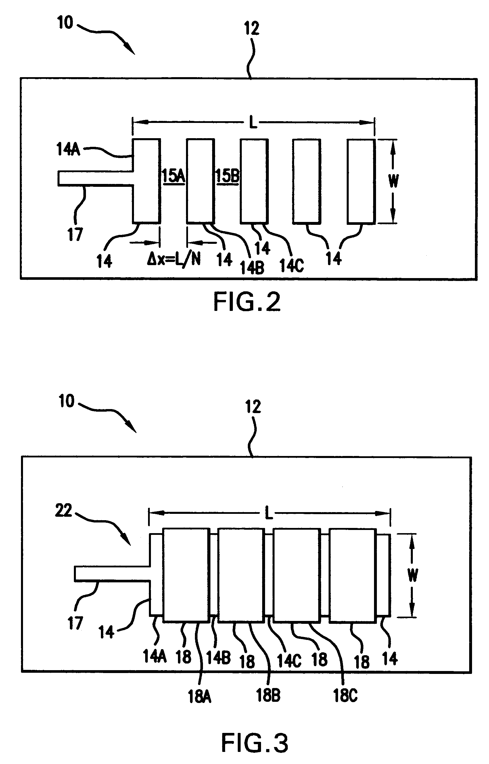
[0020]Referring to FIGS. 1–3, there is shown microstrip patch antenna 10 of the present invention. Microstrip patch antenna 10 comprises substrate 12 of grounded dielectric material. The material from which substrate 12 is fabricated depends upon the frequency of operation. Suitable materials that can be used to fabricate substrate 12 include Teflon™, FR4 and Duroid. Preferably, substrate 12 is generally planar and is substantially rectangular shape. Microstrip patch antenna 10 further comprises N primary segments 14 of electrically conductive material that are disposed over substrate 12. In a preferred embodiment, each primary segment 14 is configured as single strip or piece of metal that has a substantially flat or planar top surface. In one embodiment, primary segments 14 are plated onto substrate 12 in accordance with techniques known in the art. Preferably, the metal selected for use in fabricating primary segments 14 has excellent electrical conductivity characteristics. Exam...


PUM


Abstract

A segmented patch antenna has a dielectric material substrate, a plurality of primary electrically conductive segments consecutively disposed on the dielectric material substrate and spaced apart so that a portion of the substrate is exposed between any pair of adjacent primary segments, and a layer of dielectric material disposed over the primary segments. Secondary electrically conductive segments are disposed over the layer of dielectric material wherein each secondary segment corresponds to a pair of adjacent primary segments. Each secondary segment overlaps a portion of each primary segment of the corresponding pair of adjacent primary segments to which that secondary segments corresponds. The overlap of each secondary segment with a portion of each primary segment in a pair of adjacent primary segments produces a plurality of capacitive gaps that capacitively couple the primary and secondary segments together to define a single antenna.

Description

STATEMENT OF GOVERNMENT INTEREST[0001]The invention described herein may be manufactured and used by or for the Government of the United States of America for governmental purposes without the payment of any royalties thereon or therefor.BACKGROUND OF THE INVENTION[0002](1) Field of the Invention[0003]The present invention generally relates to a patch antenna, and more particularly to a microstrip patch antenna.[0004](2) Description of the Prior Art[0005]A typical prior art microstrip patch antenna consists of a rectangular metallic “patch” that is printed on top of a grounded slab of dielectric material. Such a microstrip patch antenna suffers from limited bandwidth as a result of its resonant properties. Bandwidth of patch antennas is typically limited to 1–3% of the antenna's center frequency. This characteristic is due to the resonant properties of the antenna.[0006]The prior art discloses several antenna structures. Yu U.S. Pat. No. 4,218,682 and Josypenko U.S. Pat. No. 6,118,4...

Claims


Application Information

Patent Timeline
Patent Type & Authority Patents(United States)
IPC IPC(8): H01Q1/38
CPCH01Q9/0442H01Q9/0407
Inventor TONN, DAVID A.
Owner THE UNITED STATES OF AMERICA AS REPRESENTED BY THE SECRETARY OF THE NAVY
Why Eureka
Try Eureka