Multi-purpose coiled tubing handling system

a technology of handling system and coiled tubing, which is applied in the direction of sealing/packing, drilling pipes, and well accessories, etc., can solve the problems of significant problems in the existing handling system of coiled tubing, and achieve the effect of minimizing the rocking of the injector

Inactive Publication Date: 2006-06-20
SCHLUMBERGER TECH CORP
View PDF7 Cites 31 Cited by
  • Summary
  • Abstract
  • Description
  • Claims
  • Application Information

AI Technical Summary

Benefits of technology

[0012]As previously described, there are significant problems with existing coiled tubing handling systems. The present invention provides an improved system for handling coiled tubing, particularly for off-shore applications. Without limiting the scope of the invention, the system provides a flexible connection between the wellhead and the coiled tubing stack and also includes a mechanism for reducing the load placed on the wellhead by the coiled tubing.
[0013]In order to allow movement between the wellhead and the coiled tubing unit, thereby allowing for compensation for movement of the wellhead in relation to the CT unit, a flexible connection is provided. In addition to allowing for movement of the wellhead or coiled tubing unit / BOP during operations, the flexible riser also allows for faster rig-up by decreasing the accuracy required to mate or join the coiled tubing unit to the wellhead.
[0015]The present invention may also be used in a derrick where no block compensation is available, such as a spar. The frame is supported in the blocks and guide wired or otherwise secured to the derrick by other suitable mechanisms. The riser is then connected to the compensation system within the frame, thereby allowing the frame to compensate for movement of well in relation to derrick. The advantage of the present system from current systems is two fold, first movement between the wellhead and the coiled tubing unit is compensated and second the ability to fix the injector tension frame with relation to derrick, thus minimizing rocking of injector while still allowing compensation.

Problems solved by technology

As previously described, there are significant problems with existing coiled tubing handling systems.

Method used


Image

  • Multi-purpose coiled tubing handling system
  • Multi-purpose coiled tubing handling system
  • Multi-purpose coiled tubing handling system

Examples


Embodiment Construction

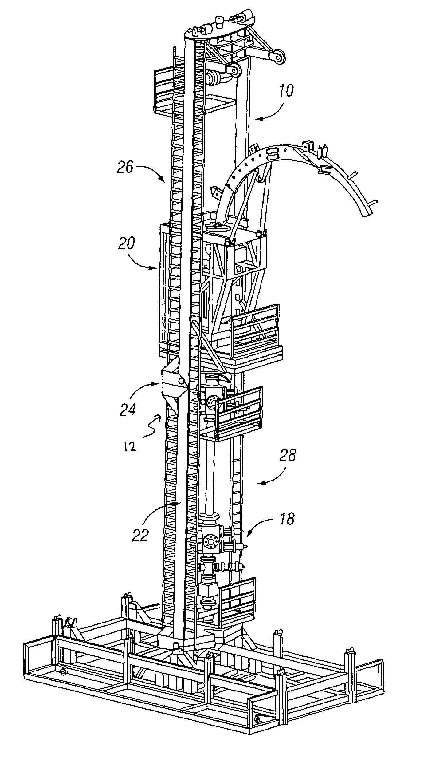
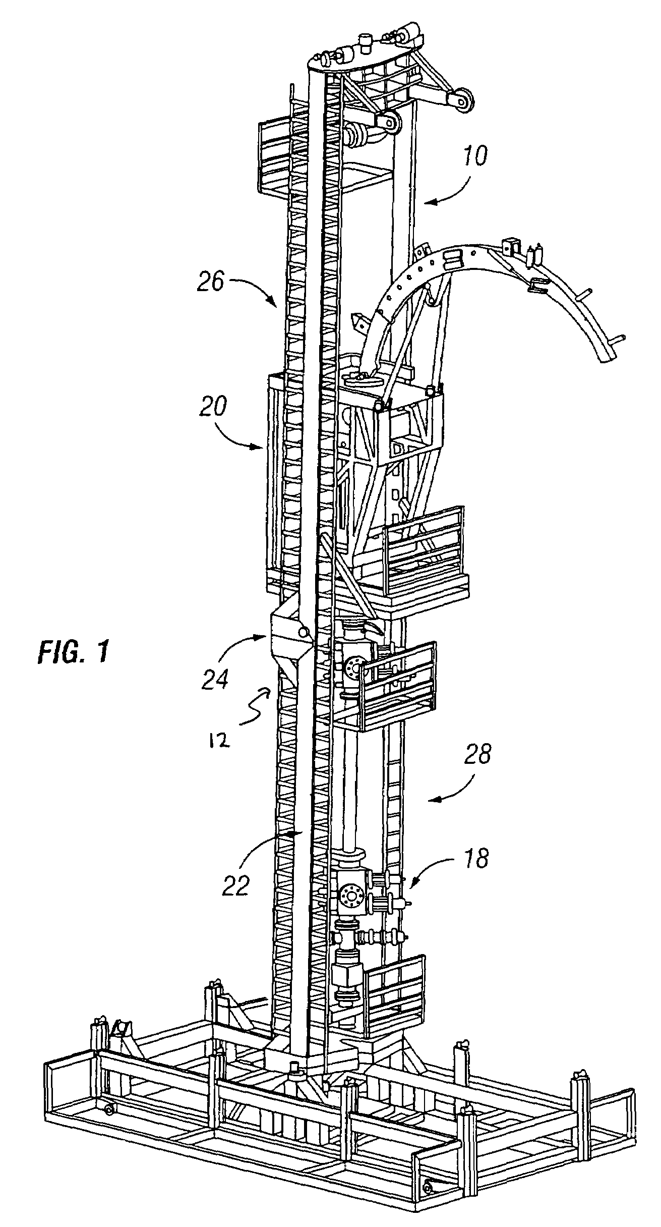
[0023]As shown in FIGS. 1, 2 and 5, the present invention includes a frame 10, a load compensation system or mechanism 12 and a flexible riser system 14 for reducing the load on the wellhead 16 and allowing both horizontal and vertical movement between the BOPs 18, coiled tubing stack 20 and the wellhead.

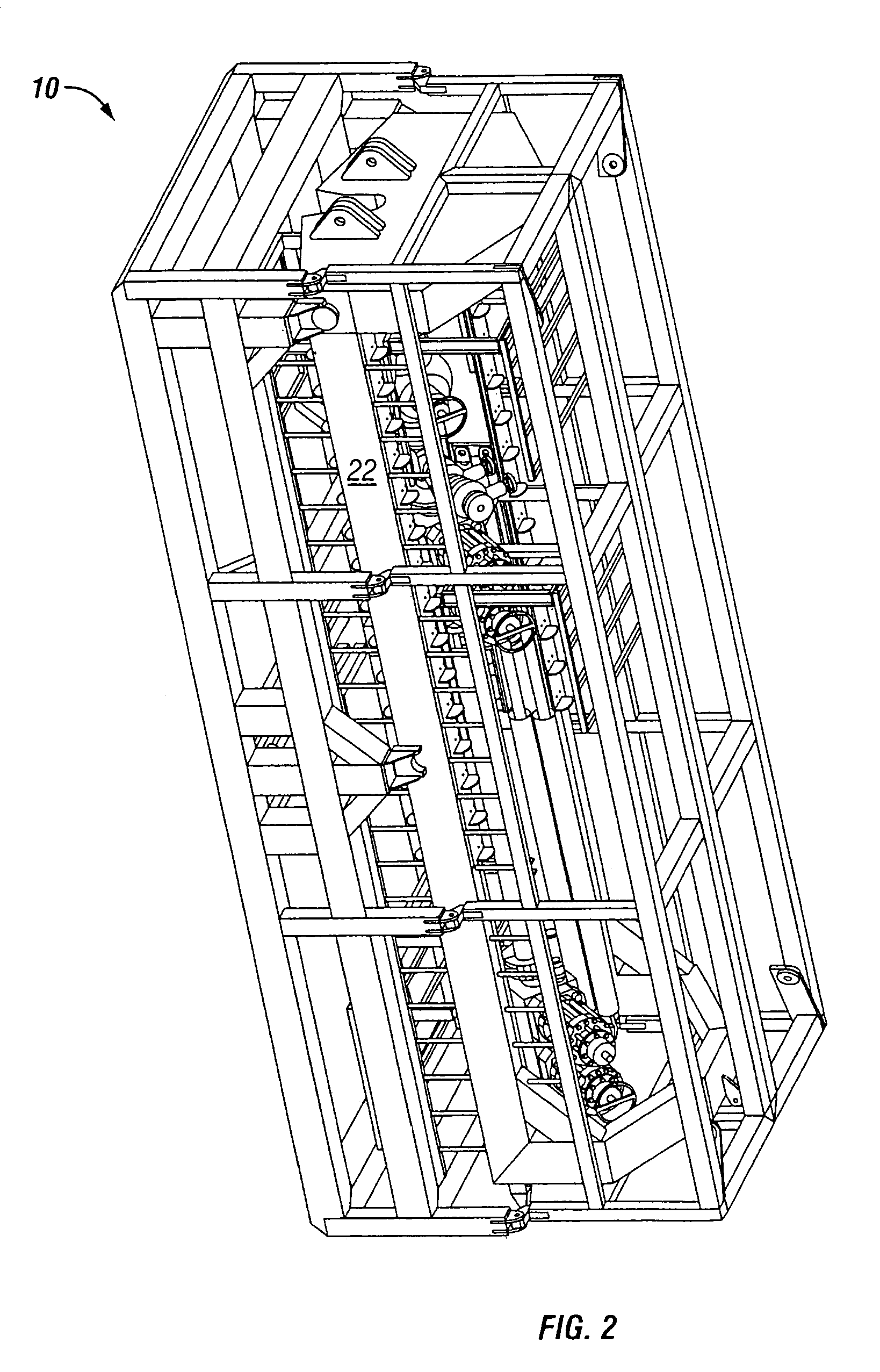
[0024]The frame 10 of the invention is typically formed from plurality of steel legs; however, any suitable material may be used to form the legs. In a preferred embodiment of the invention, the frame 10 consists of two or more vertical members or legs 22. In a more preferred embodiment, the frame is a jacking frame or tension lift frame. The legs 22 may each be a single continuous unit or may include a joint 24 thereby allowing the frame to be separated into an upper half or component 26 and a lower half or component 28. In this way, the frame may be condensed, folded or disassembled when not in use, thereby significantly decreasing the space required transport the frame to and fro...


PUM


Abstract

A system for reducing the effects of heave movements of a wellhead in an offshore drilling device is provided that includes a frame; a coiled tubing stack supported by the frame; and a heave compensation system for controlling an amount of load transferred from the coiled tubing stack to the wellhead to reduce relative movements between the coiled tubing stack and the wellhead.

Description

[0001]This patent application claims priority under 35 U.S.C. § 119(e) to provisional application Ser. No. 60 / 457,219 filed on Mar. 25, 2003 which is incorporated herein by reference.BACKGROUND OF TEE INVENTION[0002]1. Field of the Invention[0003]The present invention relates generally to an improved system for handling coiled tubing on an offshore platform or installation. More specifically, the invention is a system for reducing the load (i.e., stack weight, tubing load, etc.) on the wellhead and for providing a flexible connection between the wellhead and the coiled tubing stack.[0004]2. Description of the Prior Art[0005]There are three broad classes of offshore installations: floating platforms or floaters, fixed leg, and tension leg. Floating platforms are connected only to the sea floor by a marine riser. Fixed leg platforms have solid legs that reach all the way to the sea floor. Tension leg platforms (including spars) have cables that pull the buoyant structure deeper into t...

Claims


Application Information

Patent Timeline
Patent Type & Authority Patents(United States)
IPC IPC(8): E21B19/09E21B17/01E21B19/00E21B19/22E21B33/043
CPCE21B17/01E21B19/22E21B19/09E21B19/006
Inventor PATTON, BARTLEY J.ROD, SHAMPINEHOBBS, NIKKIMCCAFFERTY, TERRYMALLALIEU, ROBIN
Owner SCHLUMBERGER TECH CORP
Why Eureka
Try Eureka