Multi-purpose spotlight and power station

a power station and multi-purpose technology, applied in the field of multi-purpose devices, can solve the problems of combining functions of devices introduced previously, and not offering innovative features, etc., and achieve the effect of small and easy-to-portability form factor

Inactive Publication Date: 2006-06-20
SZE TAI YUNG
View PDF19 Cites 11 Cited by
  • Summary
  • Abstract
  • Description
  • Claims
  • Application Information

AI Technical Summary

Benefits of technology

[0010]Yet another objective of the invention is to provide such a device in a small and easily portable form factor.

Problems solved by technology

Various types of automotive devices have been introduced to the market, however, no device introduced previously nor now available combines the functions present in the current invention, nor do they offer the innovative features contained therein.

Method used


Image

  • Multi-purpose spotlight and power station
  • Multi-purpose spotlight and power station
  • Multi-purpose spotlight and power station

Examples


Embodiment Construction

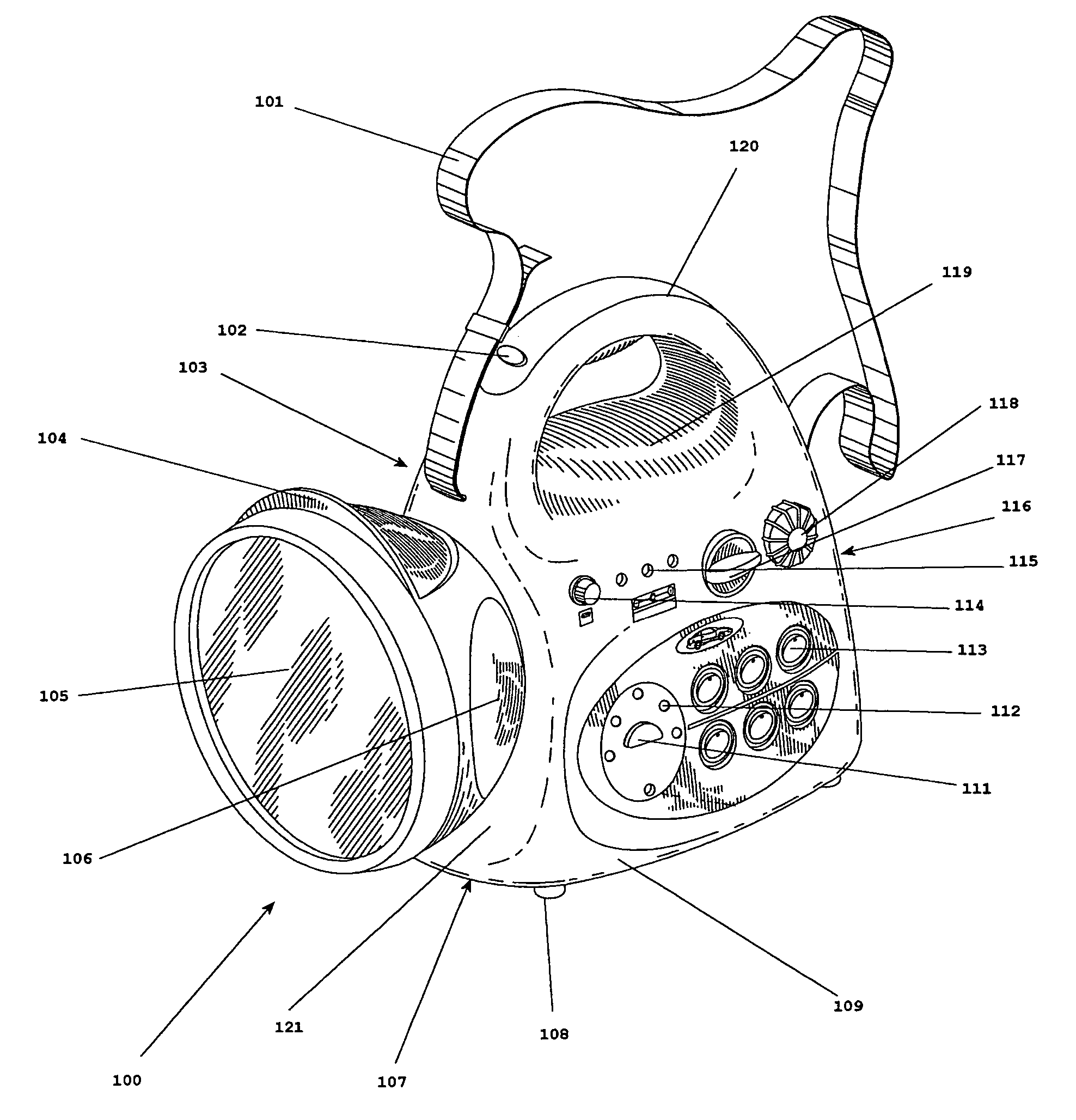
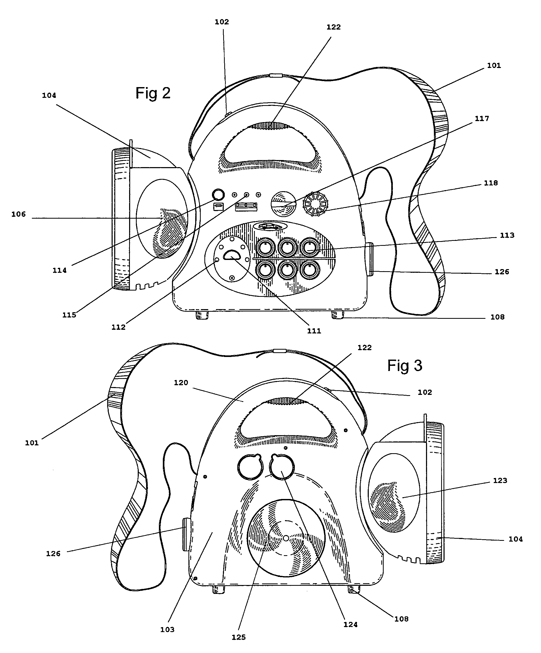
[0023]Without any intent to limit the scope of this invention, reference is made to the figures in describing the preferred embodiments of the invention. Referring to FIGS. 1 through 8, body 100 is pictured, which serves as the housing for the invention disclosed. Such body 100 is formed by front wall 121, rear wall 116, first side wall 109, second side wall 103, top wall 119, and base 107. These outer walls are where most components of the invention are located.

[0024]Handle 120 is formed in the top of body 100 so that the device can be easily carried. Another method of carrying the device is the use of strap 101 which is attached at at least two points on body 100, such as two opposite ends of top wall 119 as shown in the FIGs.

[0025]Power hub 132 is, in the exemplary embodiment, located within body 100, and serves to distribute power received from an energy source, such as from external power receptacle 129 and / or energy cell 131 to the device's components. Either power source may ...


PUM


Abstract

According to the present invention, the device disclosed is a unified structure which combines various implements useful for automotive applications. Such implements include various lighting devices, a range of power outlets, signal lamps and more. The present invention also includes an independent power supply for such devices as well as the ability to be powered from an outside source, such as a vehicle.

Description

[0001]This application is a continuation-in-part of U.S. patent application Ser. No. 29 / 187,298, filed on Jul. 30, 2003 now U.S. Pat. No. D511851 which is hereby incorporated by reference in its entirety.BACKGROUND OF THE INVENTION[0002]The present invention relates to a multi-purpose device which provides various functions to travelers. Specifically, a device for use with twelve volt power systems of automobiles which provides lighting, power outlets, and more is disclosed.[0003]Due to the dynamic nature of an automotive traveler's needs, and because of the restricted physical space generally available in automotive conveyance, it is desirable to combine the functions of several devices into a unitary design. This advantage, coupled with an offering of well-thought out additions, makes the present invention a novel and useful product offering.[0004]Various types of automotive devices have been introduced to the market, however, no device introduced previously nor now available comb...

Claims


Application Information

Patent Timeline
Patent Type & Authority Patents(United States)
IPC IPC(8): F21L4/04F21L4/02F21L14/02F21V9/08F21V23/04F21V33/00
CPCF21L4/02F21L14/023F21V23/0414F21V33/00F21Y2101/02F21V9/08F21Y2115/10
Inventor SZE-TAI, YUNG
Owner SZE TAI YUNG
Why Eureka
Try Eureka