

Method and device for producing laminated composite
a laminated composite and manufacturing method technology, applied in the direction of synthetic resin layered products, manufacturing tools, other domestic articles, etc., can solve the problems of affecting the quality of laminated composites, etc., to achieve high efficiency and high efficiency
Inactive Publication Date: 2006-06-20
SEKISUI CHEM CO LTD
View PDF22 Cites 17 Cited by
- Summary
- Abstract
- Description
- Claims
- Application Information
AI Technical Summary
Benefits of technology
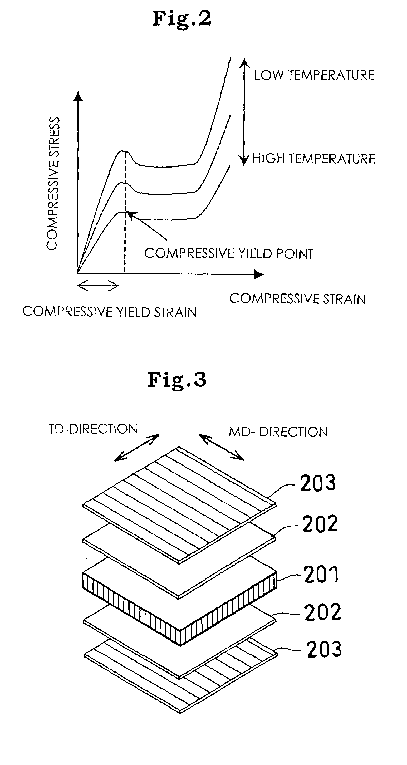
The invention is a method and device for producing a laminated composite by laminating a polyolefin resin drawn sheet onto a sheet-form core material using a bonding synthetic resin or rubber as a bonding agent. The method involves heating the core material and the drawn sheet with a flow starting temperature lower than the thermal deformation temperature of the core material and the drawn sheet, and pressing them together to apply a compression strain of 0.01 to 10% to the core material. The resulting laminated composite has improved mechanical properties and is suitable for use in various applications.
Problems solved by technology
However, if the reinforcing face material is heated to the melting point thereof or higher in order to attempt the production of this composite lamination by the method described in Japanese Unexamined Patent Publication No. 6-134913 (1994), the drawn orientation of the molecules is lost since the reinforcing face material is made of the polyolefin resin drawn sheet.
As a result, desired flexural-rigidity and linear expansion property cannot be obtained.
Furthermore, a problem that the thickness of manufactured product is scattered arises.
Thus, a problem that construction work becomes much complicated is involved.
In this method, however, the operation for producing the lamination is intermittent; therefore, the speed of the production is small and a large amount of scrap material is generated and production efficiency is low, thereby resulting in high costs.
Method used
View moreImage
Smart ImageViewing Examples

Examples
example 1
Drawn Sheet / Two Synthetic Resin Films / Foamed Body Sheet / Two Synthetic Resin Films / Drawn Sheet
example 2
Drawn Sheet / Synthetic Resin Film / Synthetic Resin Impregnated Foamed Body Sheet / Synthetic Resin Film / Drawn Sheet
example 3
Synthetic Resin Film Laminated Drawn Sheet / Synthetic Resin Film / Foamed Body Sheet / Synthetic Resin Film / Synthetic Resin Film Laminated Drawn Sheet
Login to View More PUM
| Property | Measurement | Unit |
|---|---|---|
| density | aaaaa | aaaaa |
| tension | aaaaa | aaaaa |
| aspect ratios | aaaaa | aaaaa |
Abstract
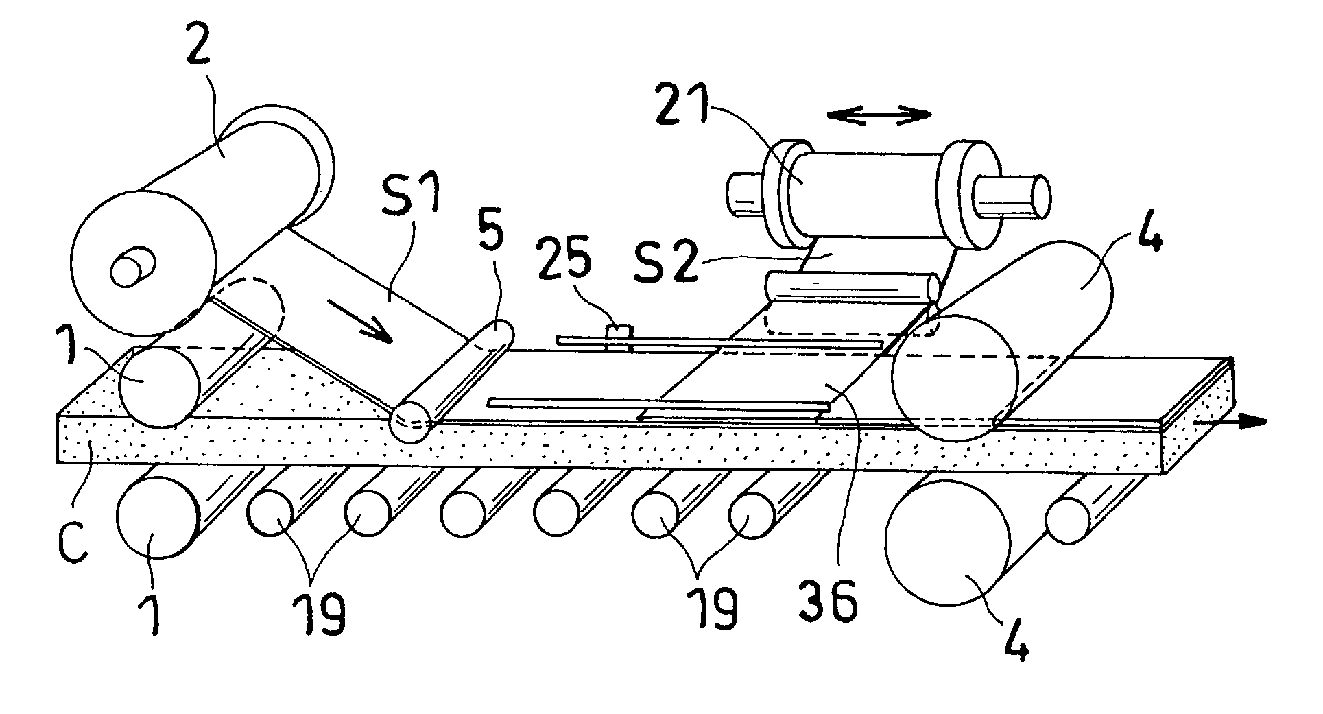
A polyolefin resin drawn sheet 4 is laminated on at least one face of a sheet-form core material 6 having a density of 30 to 300 kgf / m3. At this time, a sheet or film 5 made of a bonding synthetic resin or rubber having a flow starting temperature lower than the thermal deformation temperature of the core material 6 and the melting point of the drawn sheet 4 is interposed between the core material 6 and the drawn sheet 4. The resultant stack product is heated to not less than the flow starting temperature of the synthetic resin or the rubber and not more than the thermal deformation temperature of the core material 6 and the melting point of the drawn sheet 4. At the same time of or after the heating, the stack product is pressed to apply a compression strain of 0.01 to 10% to the core material 6.
Description
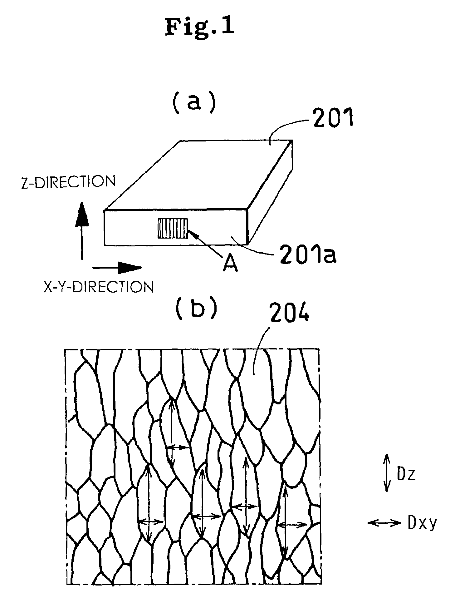
TECHNICAL FIELD[0001]The present invention relates to a method and a device for producing a laminated composite which is used as a civil engineering and construction material, a construction material including a tatami mat core material, a material for vehicles and so on, and has a high rigidity, and more specifically to a device and a method for producing a laminated composite which is suitable, for example, when a polyolefin resin drawn sheet is laminated on at least one face of a sheet-form core material having a density of 30 to 300 kg / m3, or when a longitudinal sheet and a lateral sheet are laminated on at least one face of a core material.[0002]Throughout the present specification, longitudinal and lateral directions are defined on the basis of the direction of a core material. The term “longitudinal” means the length direction of a core material, and the term “lateral” means the width direction of the core material. A longitudinal sheet means a sheet supplied in the length di...
Claims
Login to View More Application Information
Patent Timeline
 Patent Type & AuthorityPatents(United States)
IPC IPC(8): B32B37/00B32B5/18B32B27/08B32B27/32B32B37/08B32B38/00
CPCB32B5/18B32B27/32B32B37/04B32B37/1207B32B38/1816B32B27/08Y10T156/1712B32B37/08B32B38/0036B32B2037/148B32B2037/243B32B2038/0028B32B2305/022B32B2307/306B32B2307/516B32B2307/748B32B2471/04
InventorTSUJIMOTO, MICHITAKAMATSUZAKA, KATSUOYAMAGUCHI, KOJIOKABE, MASASHIHIRATA, MASANORIISHIYAMA, MASAFUMI
OwnerSEKISUI CHEM CO LTD