
Method for the generation of variable pitch nested lines and/or contact holes using fixed size pixels for direct-write lithographic systems

a lithographic system and fixed size technology, applied in the direction of photographic processes, instruments, electric digital data processing, etc., can solve the problems of image limitations, complex pixel layout over a continuous range of pitches,

Active Publication Date: 2006-06-20
ASML HLDG NV
View PDF2 Cites 211 Cited by
  • Summary
  • Abstract
  • Description
  • Claims
  • Application Information

AI Technical Summary

Benefits of technology

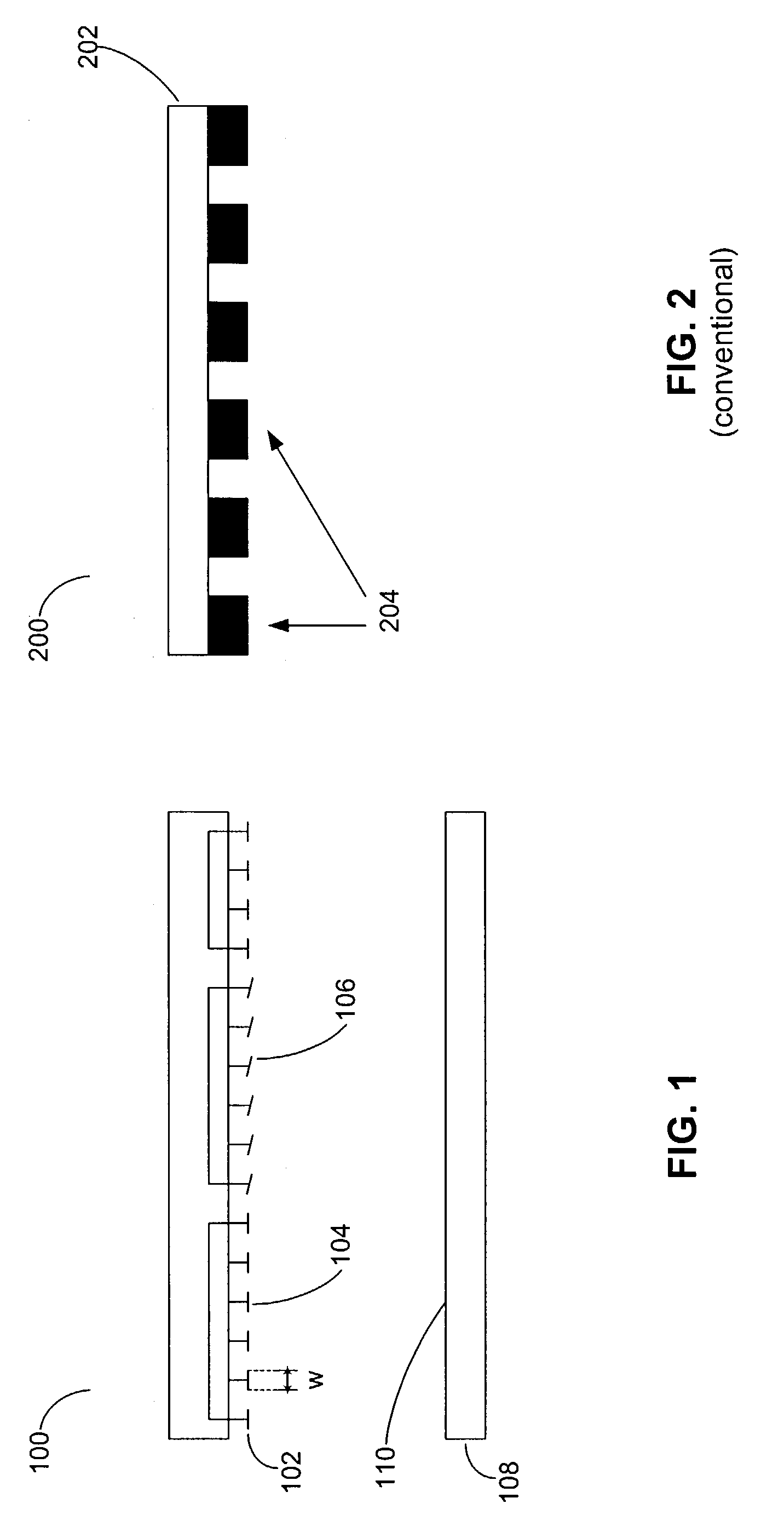
[0012]The present invention provides a systematic approach to generating mask layouts using an array of fixed shape mirrors of fixed size to print grouped lines and contacts over a continuous range of pitches. This is particularly useful in the field of Maskless Lithography where the goal is to ensure that patterns can be printed over a wide range of pitches independently of the pitch of the mirror array.

Problems solved by technology

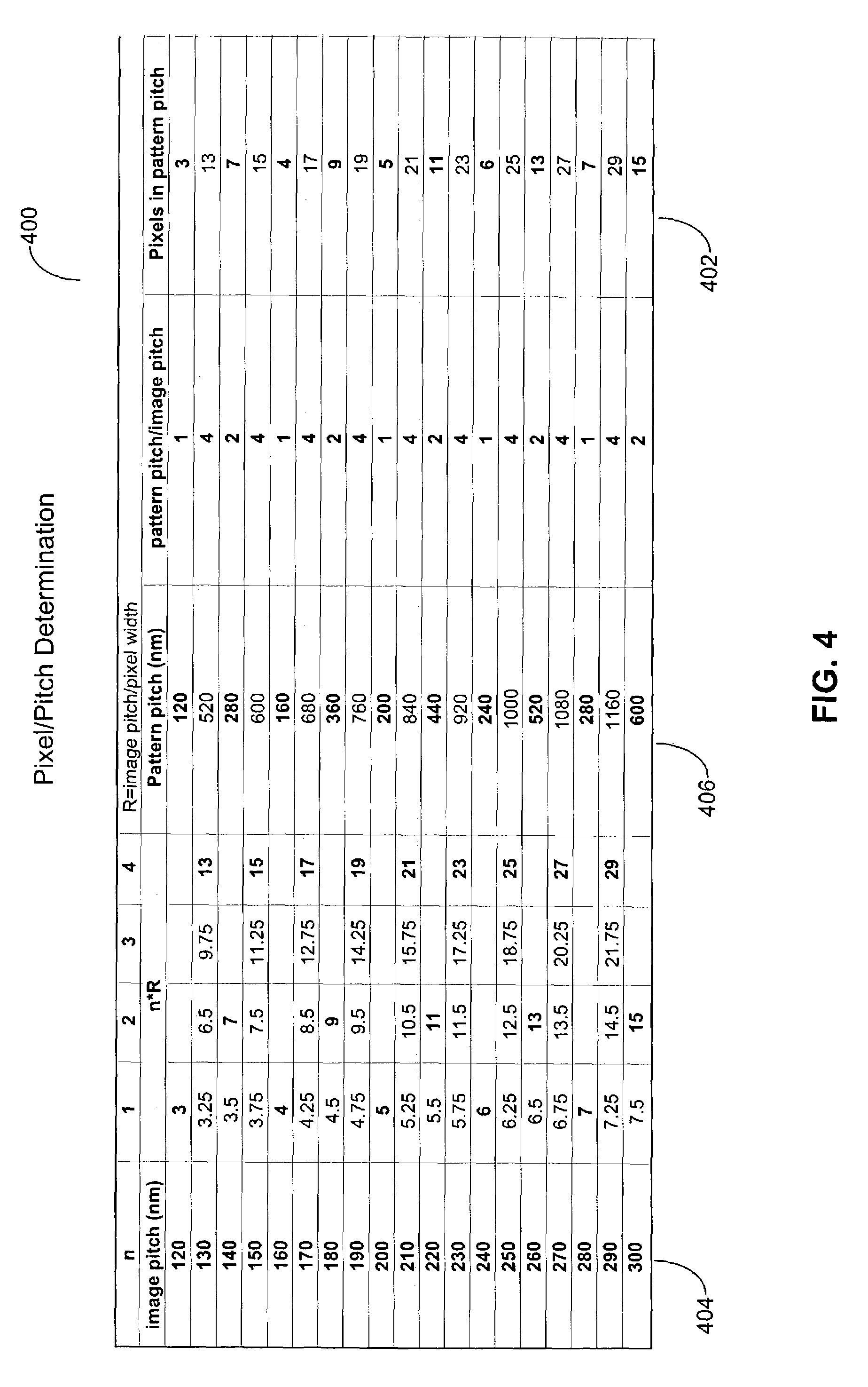
However, finding an adequate pixel layout over a continuous range of pitches for grouped patterns can be complicated and requires a systematic approach for not only generating images with the appropriate pitch and periodicity, but also for generating images that will meet standard image quality requirements.
One of the issues contributing to some degradation in images produced by maskless reticles is that these images face some limitations due to size and other restrictions associated with the dimensions and characteristics of the mirrors.
However, due to the size and other limitations of the pixels and because of the increasingly small and diverse patterns that are being targeted in deep ultraviolet (DUV) lithography, the CD or pitch of these patterns might not be a multiple of the pixel size, as noted above.

Method used


Image

  • Method for the generation of variable pitch nested lines and/or contact holes using fixed size pixels for direct-write lithographic systems
  • Method for the generation of variable pitch nested lines and/or contact holes using fixed size pixels for direct-write lithographic systems
  • Method for the generation of variable pitch nested lines and/or contact holes using fixed size pixels for direct-write lithographic systems

Examples


Embodiment Construction

[0026]The following detailed description of the present invention refers to the accompanying drawings that illustrate exemplary embodiments consistent with this invention. Other embodiments are possible, and modifications may be made to the embodiments within the spirit and scope of the invention. Therefore, the following detailed description is not meant to limit the invention. Rather, the scope of the invention is defined by the appended claims.

[0027]It would be apparent to one of skill in the art that the present invention, as described below, may be implemented in many different embodiments of hardware, software, firmware, and / or the entities illustrated in the drawings. Any actual software code with the specialized controlled hardware to implement the present invention is not limiting of the present invention. Thus, the operation and behavior of the present invention will be described with the understanding that modifications and variations of the embodiments are possible, give...


PUM

PropertyMeasurementUnit
sizeaaaaaaaaaa
widthaaaaaaaaaa
widthaaaaaaaaaa

Abstract

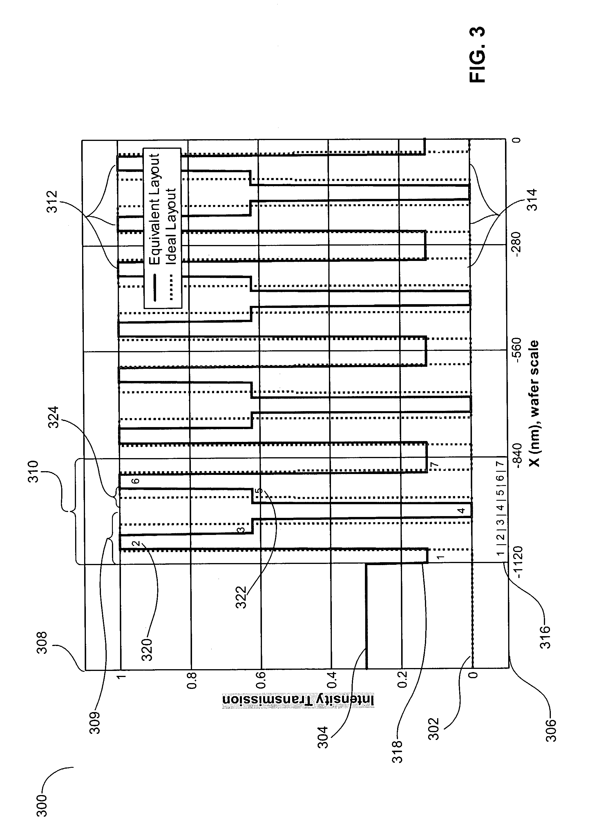
Provided is a method and system for developing a lithographic mask layout. The lithographic mask layout is adapted for configuring an array of micro-mirrors in a maskless lithography system. The method includes generating an ideal mask layout representative of image characteristics associated with a desired image. Next, an equivalent mask is produced in accordance with an average intensity of the ideal mask layout.

Description

BACKGROUND OF THE INVENTION[0001]1. Field of the Invention[0002]The present invention is directed to pattern generation in photolithography systems.[0003]2. Related Art[0004]In maskless lithography systems, image patterns are generated by a micro-array of mirrors at an object plane of a target wafer. These mirrors can be tilted in a controlled manner to produce grey-scaling. On the wafer scale, these mirrors (pixels) can be demagnified to as little as a few tens of nanometers. In spite of this, because of the increasingly small and diverse patterns that are being targeted in deep ultraviolet (DUV) lithography, the critical dimension (CD) or pitch of these patterns is not necessarily a multiple of the pixel size.[0005]CD and pitch are not necessarily big limitations for isolated patterns. However, finding an adequate pixel layout over a continuous range of pitches for grouped patterns can be complicated and requires a systematic approach for not only generating images with the approp...

Claims


Application Information

Patent Timeline
Patent Type & Authority Patents(United States)
IPC IPC(8): G03F9/00G03F1/00G03F1/70G03F7/00G03F7/20G06F17/00G06F17/50H01L21/027
CPCG03F1/14G03F1/70G03F7/2051G03F7/70433G03F7/70283G03F7/70291G03F7/2053G03F1/62G03F7/70383
Inventor BABA-ALI, NABILA
Owner ASML HLDG NV
Learn More