Recessed electrode for electrostatically actuated structures

a technology of electrostatic actuators and electrodes, applied in the field of microelectromechanical systems, can solve the problems of increasing the likelihood of stiction, and reducing the gap distance between electrodes, so as to achieve the effect of lowering the actuation voltag

Inactive Publication Date: 2006-06-20
AAC TECH PTE LTD
View PDF6 Cites 59 Cited by
  • Summary
  • Abstract
  • Description
  • Claims
  • Application Information

AI Technical Summary

Benefits of technology

[0006]It is an object of the present invention to provide a design feature that allows lower actuation voltage for electrostatically actuated structures (i.e., switches or mirrors).
[0008]It is another object of the present invention to provide an electro-statically actuated switch having a reduced gap distance between electrodes for reducing actuation voltage.
[0009]It is a further object of the present invention to provide a more reliable electro-statically actuated switches.
[0010]It is yet another object of the present invention to provide electro-statically actuated switches that reduce the likelihood of stiction and beam deformation.

Problems solved by technology

A problem associated with increasing the length of the beam is that the beam becomes more compliant, thus increasing the likelihood of stiction, i.e., a condition wherein the movable beam will not revert back to an “open” position from a “closed” position.
Also, reducing the gap distance between the electrodes can increase the likelihood of stiction.
Furthermore, reducing the gap distance between the electrodes can increase the difficulty in forming the protruding contacts because there is less available area beneath the movable beam to do so.
Another problem with reducing the gap distance is that any stress and curvature of the beam can lead to contact of the electrodes, thus shorting the electrodes.

Method used


Image

  • Recessed electrode for electrostatically actuated structures
  • Recessed electrode for electrostatically actuated structures
  • Recessed electrode for electrostatically actuated structures

Examples


Embodiment Construction

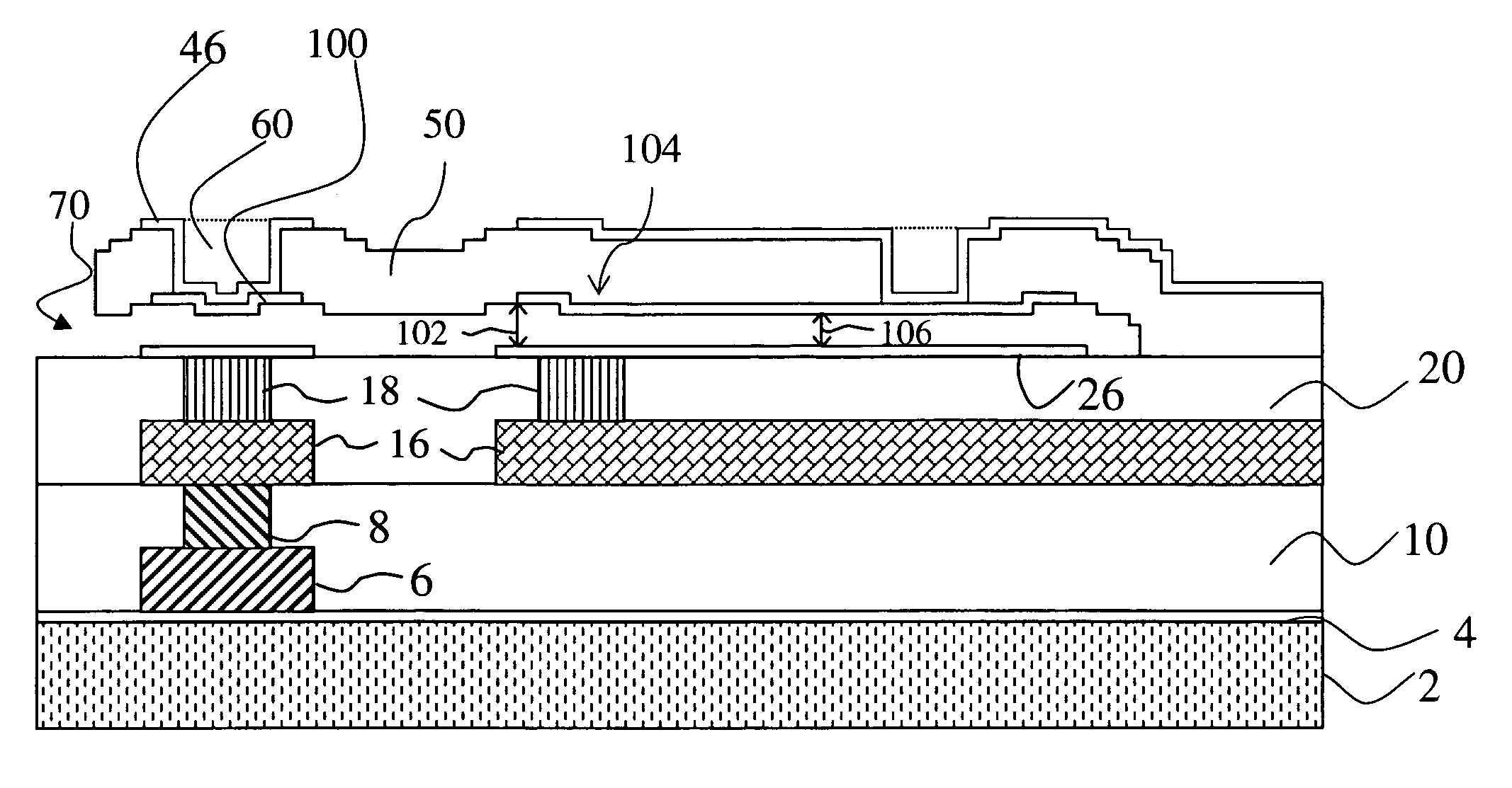
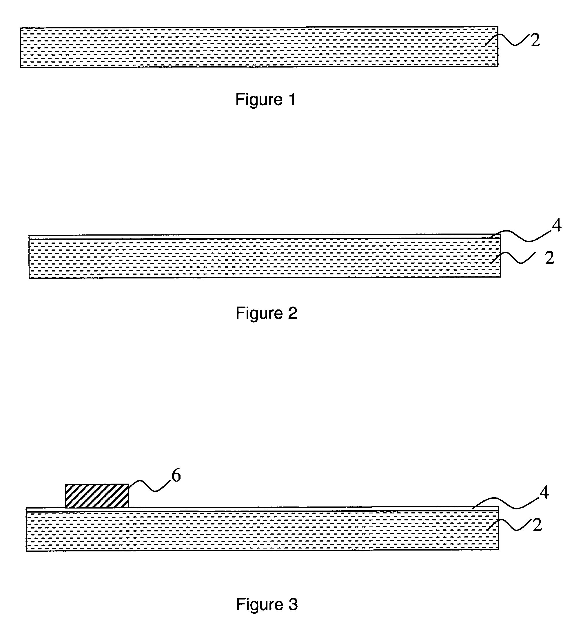
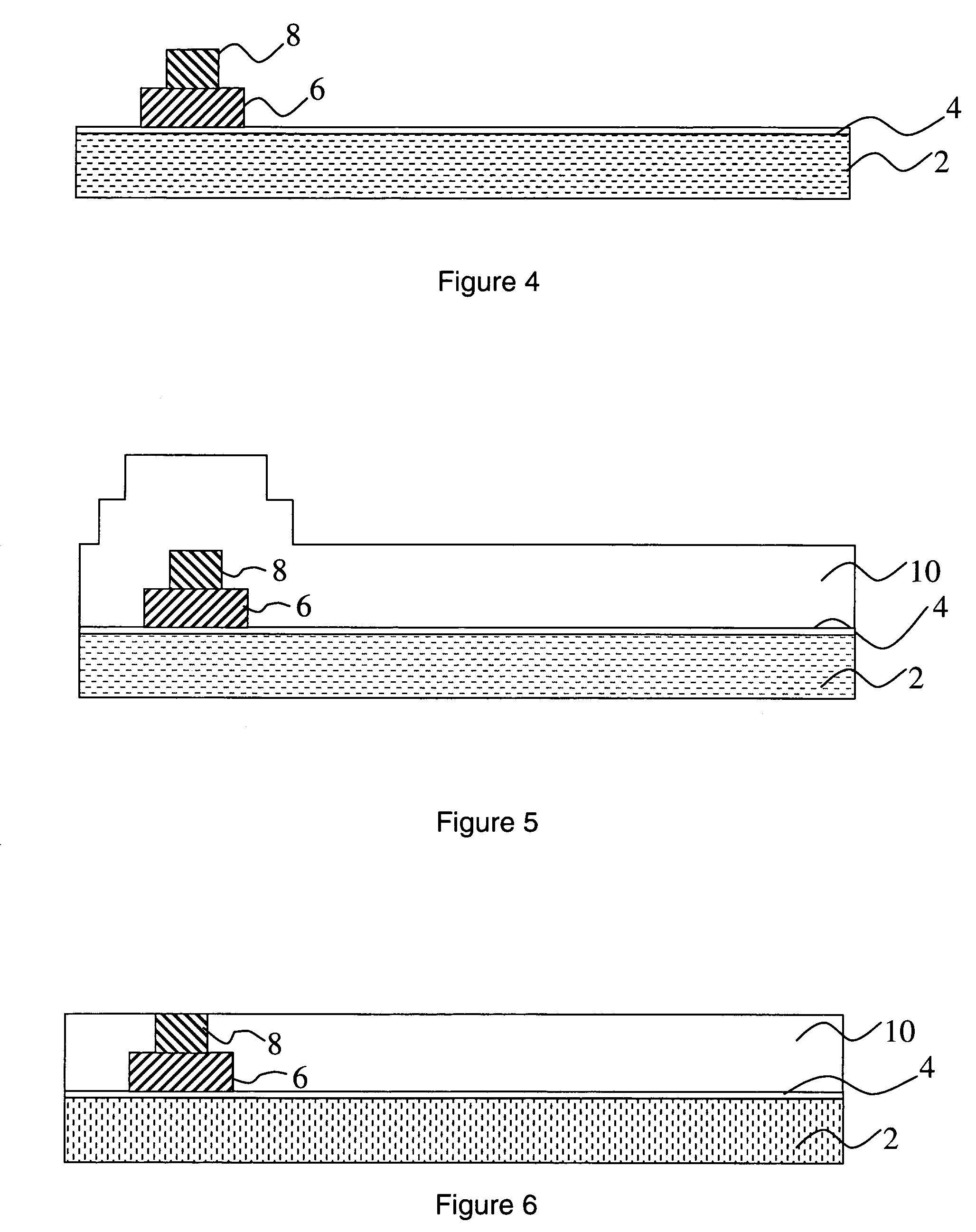
[0015]The preferred embodiments of the present invention will now be described with reference to FIGS. 1–20, wherein like structures and materials are designated by like reference numerals throughout the various figures. The inventors of the present invention disclose herein a structure and method for designing a structure that allows lower actuation voltage. Further, specific processing parameters provided herein are intended to be explanatory rather than limiting.

[0016]The process used for fabricating the structures with the recessed electrodes can be both surface-bulk-micromachining processes. In the case of surface micromachining, the process can be performed by fabricating multiple separately patterned sacrificial layers and forming a surface topology of the underside of the mechanical structure so that it is optimal from the performance standpoint. One such possible fabrication process is illustrated below.

[0017]FIGS. 1–19 illustrate one method for fabricating the structure of...


PUM

PropertyMeasurementUnit
diameteraaaaaaaaaa
diameteraaaaaaaaaa
diameteraaaaaaaaaa

Abstract

An electro-statically actuated switch having a reduced gap distance between electrodes for reducing actuation voltage is provided. The invention provides more reliable electro-statically actuated switches. The invention provides a micro-electro-mechanical system (MEMS) that includes a recessed, movable electrode. The invention provides electro-statically actuated switches that reduce the likelihood of stiction and beam deformation and that allows lower actuation voltage for electrostatically actuated structures such as switches and mirrors. A method for fabricating such a design is provided that allows lower actuation voltage.

Description

CROSS-REFERENCE TO RELATED APPLICATION[0001]This application claims the benefit of prior U.S. Provisional Application Ser. No. 60 / 396,869, filed Jul. 18, 2002, which is hereby incorporated by reference herein.FIELD OF THE INVENTION[0002]The present invention relates to micro-electro-mechanical systems (MEMS). The present invention relates to a design feature that allows lower actuation voltage for electrostatically actuated structures (i.e., switches or mirrors). The present invention further relates to a method for fabricating such a design that allows lower actuation voltage.BACKGROUND OF THE INVENTION[0003]An electrostatic MEMS switch is a switch operated by an electrostatic charge and manufactured using MEMS techniques. The MEMS switch can control electrical, mechanical, or optical signal flow, and they have application to telecommunications, such as DSL switch matrices and cell phones, Automated Testing Equipment (ATE), and other systems that require low cost switches or low-co...

Claims


Application Information

Patent Timeline
Patent Type & Authority Patents(United States)
IPC IPC(8): H01H51/22H01H59/00
CPCH01H59/0009Y10T29/49002Y10T29/49155Y10T29/49128Y10T29/49105
Inventor TACTIC-LUCIC, SVETLANASETT, SUBHAM
Owner AAC TECH PTE LTD
Why Eureka
Try Eureka