Relaxation oscillator based keypad decoder

a relaxation oscillator and keypad technology, applied in the direction of coding, instruments, pulse techniques, etc., can solve the problem of not being able to attach each button to a digital input, and achieve the effect of a simple digital keypad processor

Active Publication Date: 2006-06-20
TEXAS INSTR INC
View PDF2 Cites 16 Cited by
  • Summary
  • Abstract
  • Description
  • Claims
  • Application Information

AI Technical Summary

Benefits of technology

[0010]The keypad decoder of this invention makes use of a relaxation oscillator to detect and identify keystrokes and a simple digital keypad processor. The input portion of the digital keypad processor receives the output waveform from the relaxation oscillator and uses a timer / counter circuit to decode specific keys. A digital output of the timing function generator latches and holds a binary number key code identifying the depressed key. The digital keypad processor detects the specific key encoded and outputs this digital key code information to the host processor. This provides transient-free, noise immune keypad decoding.

Problems solved by technology

Attaching each button to a digital input is not practical.

Method used


Image

  • Relaxation oscillator based keypad decoder
  • Relaxation oscillator based keypad decoder
  • Relaxation oscillator based keypad decoder

Examples


first embodiment

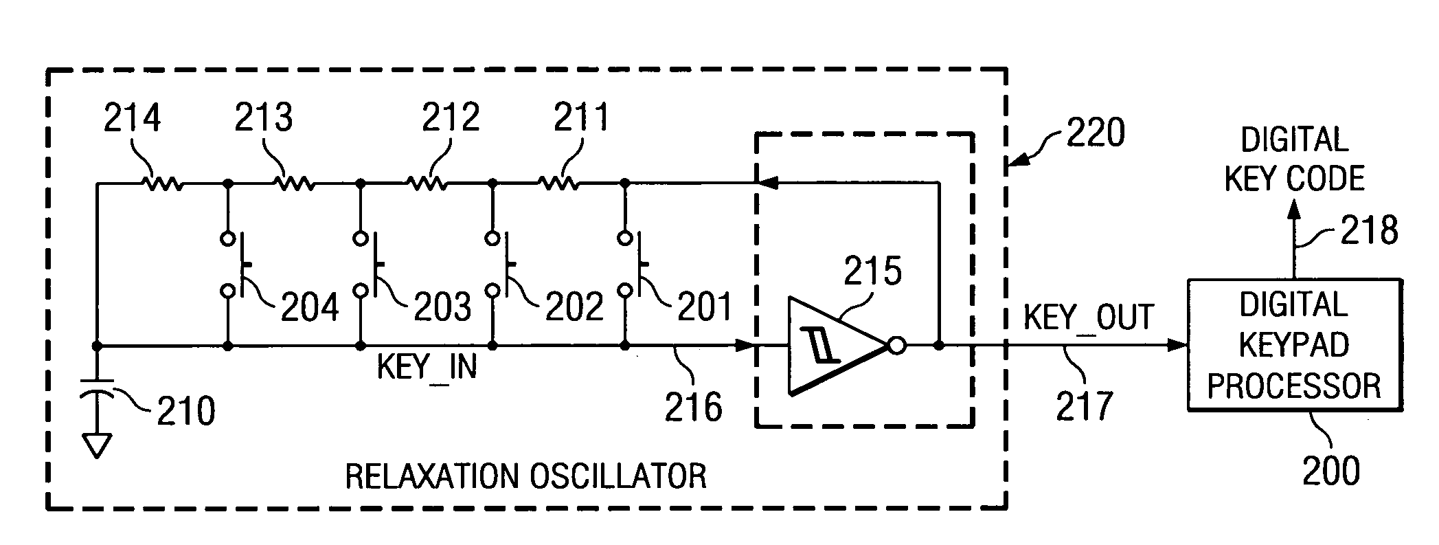
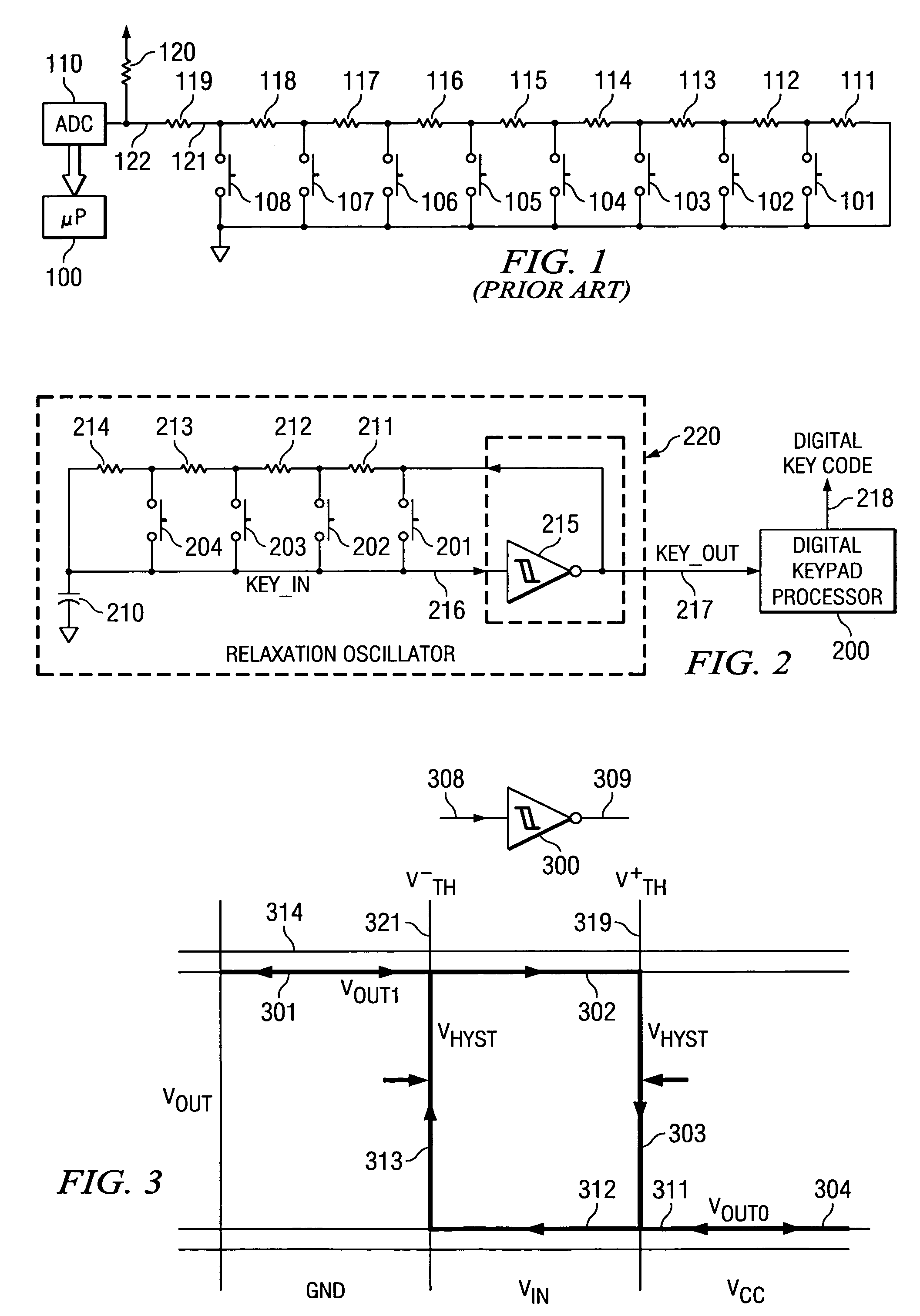
[0019]FIG. 2 illustrates the keypad decoder of this invention including relaxation oscillator 220 and digital keypad processor 200. Relaxation oscillator 220 converts pushbutton inputs into a square wave output whose frequency varies depending on the button or buttons pressed. Digital keypad processor 200 measures and records the period of the relaxation oscillator waveform and sends the measured period output to a host processor as digital key code 218. This measured period output is mapped by software into a respective key-code.

Relaxation Oscillator

[0020]Relaxation oscillator 220 generates a square wave variable frequency waveform. CMOS inverter circuit 215, the active element of relaxation oscillator 220, has a double-valued input threshold voltage that is dependent upon the direction of input voltage variations. The resulting transfer characteristic is commonly referred to as one having hysteresis. FIG. 2 illustrates a first embodiment of a plurality of possible relaxation oscil...

third embodiment

[0052]FIG. 7 illustrates the invention. The pushbuttons are organized into two banks of five pushbuttons. The relaxation oscillator of FIG. 7 also includes capacitor 710 and hysteresis inverter 700. All single key-presses can be detected as well as any input combination where one pushbutton from bank A including pushbuttons 721, 722, 723, 724 and 725 and another from bank B including pushbuttons 741, 742, 743, 744 and 745 is depressed. The resistors of bank A all have the value R. The resistors of bank B all have the value 6R, which is the sum of all resistors of bank A. Note that equal number of pushbuttons in bank A and bank B is not required. FIG. 7 merely illustrates an example where there are five pushbuttons in bank A and 5 pushbuttons in bank B. Table 2 summarizes the relationship between the pushbutton input and the resulting period for the circuit of FIG. 7.

[0053]

TABLE 2CombinationsS1S2S3S4S5OpenS6 1T 2T 3T 4T 5T 6TS7 7T 8T 9T10T11T12TS813T14T15T16T17T18TS919T20T21T22T23T24...


PUM


Abstract

The keypad interface element of this invention uses a relaxation oscillator and a digital keypad processor having a counter/timer to decode specific keys. The RC portion of the relaxation oscillator includes a resistance ladder and a set of momentary on pushbutton switches disposed change resistance dependent upon which key is pressed. This causes the relaxation oscillator to produce an output signal having a corresponding frequency. The counter/timer of the digital keypad processor produces a count corresponding to the oscillator frequency. The digital keypad processor latches and holds a binary number specifically identifying the depressed key. A state machine in the digital keypad processor provides transient-free, noise immune keypad decoding.

Description

TECHNICAL FIELD OF THE INVENTION[0001]The technical field of this invention is keypad manual input devices.BACKGROUND OF THE INVENTION[0002]A common task in the design of consumer devices is that of decoding keypad inputs from the user. Many consumer devices such as audio playback units have a keypad that permits users to navigate through play-lists and select a variety of functions. These keypads must be interfaced to the microprocessor or digital signal processor that controls the consumer device.[0003]Attaching each button to a digital input is not practical. The processors found in small consumer devices typically have a small number of general purpose input pins. Additionally, such pins are normally shared with other processor functions.[0004]A common known solution to this problem employs a binary weighted resistor ladder network and pushbuttons used as an input to an analog-to-digital converter ADC. In this type circuit each button press produces a unique voltage that is conv...

Claims


Application Information

Patent Timeline
Patent Type & Authority Patents(United States)
IPC IPC(8): H03M11/00H03M11/24
CPCH03M11/24
Inventor FEDIGAN, STEPHEN J.
Owner TEXAS INSTR INC
Why Eureka
Try Eureka