Method and apparatus for determining geometrical data of a motor vehicle wheel mounted rotatably about an axis of rotation

a technology of geometrical data and motor vehicles, which is applied in the direction of measurement devices, instruments, surveying and navigation, etc., can solve the problems of not having a geometrical axis, minimize the effect of run out and wheel unbalance, and minimize vibration

Inactive Publication Date: 2006-06-20
SNAP ON EQUIP
View PDF11 Cites 7 Cited by
  • Summary
  • Abstract
  • Description
  • Claims
  • Application Information

AI Technical Summary

Benefits of technology

[0004]The object of the invention is to provide a method and an apparatus of the kind set forth in the opening part of this specification, with which the position of the motor vehicle wheel can be determined in a simple manner.
[0005]The invention provides that the spacings of a plurality of measurement points from a reference location are measured. Those measurement points are disposed on at least two peripheries which are in two planes perpendicular to the axis of rotation about which the motor vehicle wheel is rotated. The rotary angle positions of the respective measurement points are also measured or determined. The position of the motor vehicle wheel with respect to the axis of rotation is determined from the measurement values for the respective distances of the measurement points and the associated rotary angle positions. That operation of determining the position of the motor vehicle wheel makes it possible to determine in particular the eccentricity and / or the angle of inclination of the geometrical axis of the wheel, with respect to the axis of rotation about which the motor vehicle wheel rotates.
[0008]The unbalance measurement data of one measuring run and the run out data particularly of the rim of the vehicle wheel obtained in a first positional relationship of the tyre and the rim of the vehicle wheel can be analysed by computing to match mount the tyre on the rim in a second position, wherein the effects of the run out and of the wheel unbalance are minimized. By rotating (matching) the tyre on the rim from the first rotational position to the second rotational position a positional relationship can be adjusted where the forces created by the unbalance counteract against the effects of the run out of the rim to minimize vibrations. The optimisation of the smooth running of the vehicle wheel can be performed by aligning the high spot of the run out with the low spot of the tyre (EP 0 247 350).
[0010]A triangulation measuring device known from EP 1 174 698 A2 can preferably be used for scanning and distance measurement. That triangulation measuring device not only makes it possible to determine the profile of the disc wheel and in particular the wheel rim, as is used for optimising the balancing operation, but it is also possible to determine a position of the rotatably supported motor vehicle wheel, in particular the position of its geometrical wheel axis with respect to the axis of rotation. Particularly in regard to measuring the unbalance of the motor vehicle wheel, accurate balancing parameters are achieved, in regard to which eccentric mounting of the motor vehicle wheel on the main shaft of the wheel balancing machine is also compensated. It is also possible to determine geometrical deformation of the wheel such as lateral and radial wobble or run-out. In addition it is possible to determine irregularities of the pneumatic tyre, in particular irregularities in tyre stiffness, as explained above. That therefore provides a comprehensive diagnosis of the quality of the motor vehicle wheel.

Problems solved by technology

When fixing the motor vehicle wheel to a rotatable wheel mounting, for example the main shaft of a wheel balancing machine or to the rotatable wheel fixing of a motor vehicle wheel or another wheel fixing, there is the danger that the geometrical axis of the wheel does not coincide with the axis of rotation about which the wheel rotates, for example in an unbalance measuring run or while the motor vehicle is travelling.

Method used


Image

  • Method and apparatus for determining geometrical data of a motor vehicle wheel mounted rotatably about an axis of rotation
  • Method and apparatus for determining geometrical data of a motor vehicle wheel mounted rotatably about an axis of rotation
  • Method and apparatus for determining geometrical data of a motor vehicle wheel mounted rotatably about an axis of rotation

Examples


Embodiment Construction

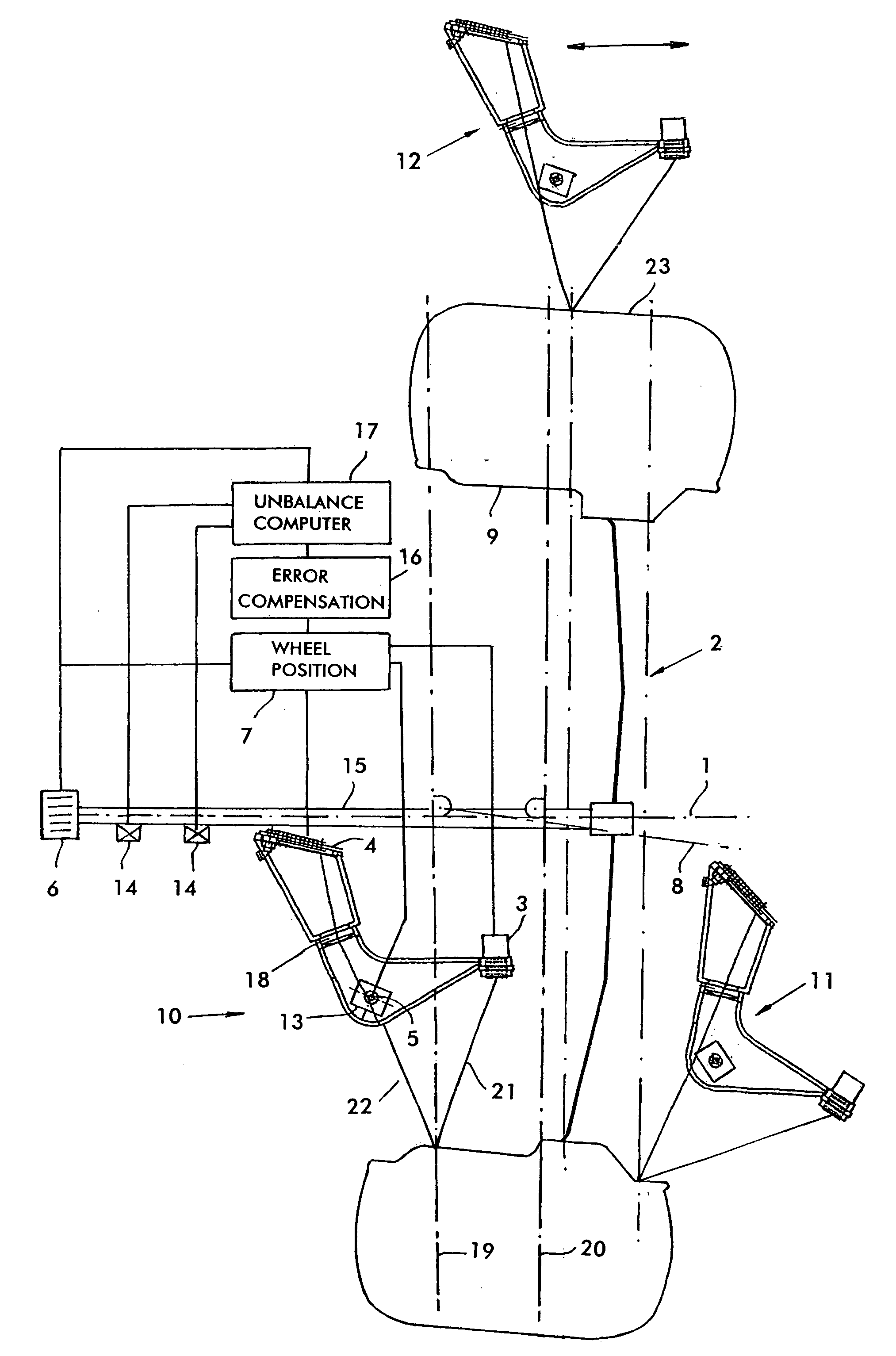
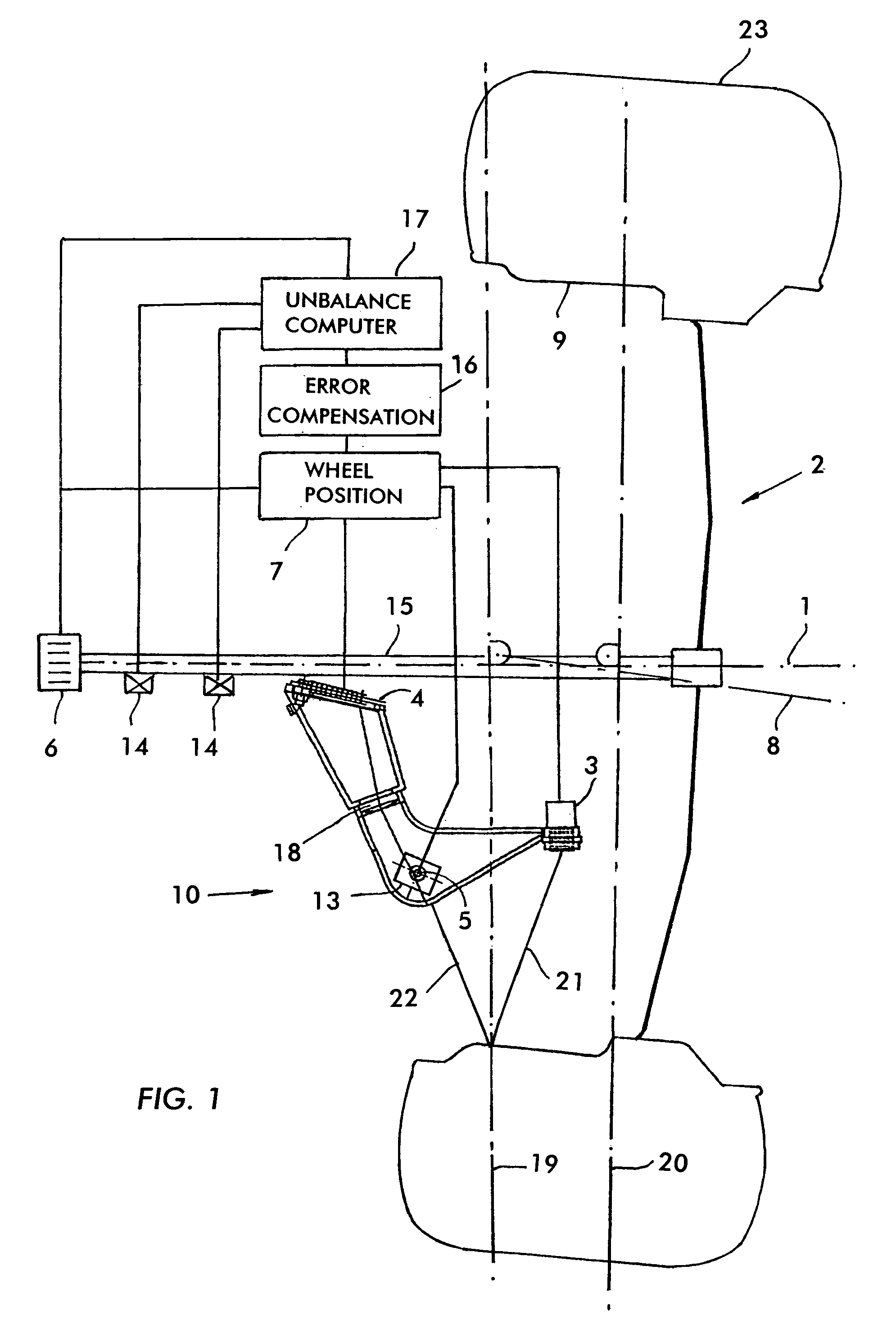
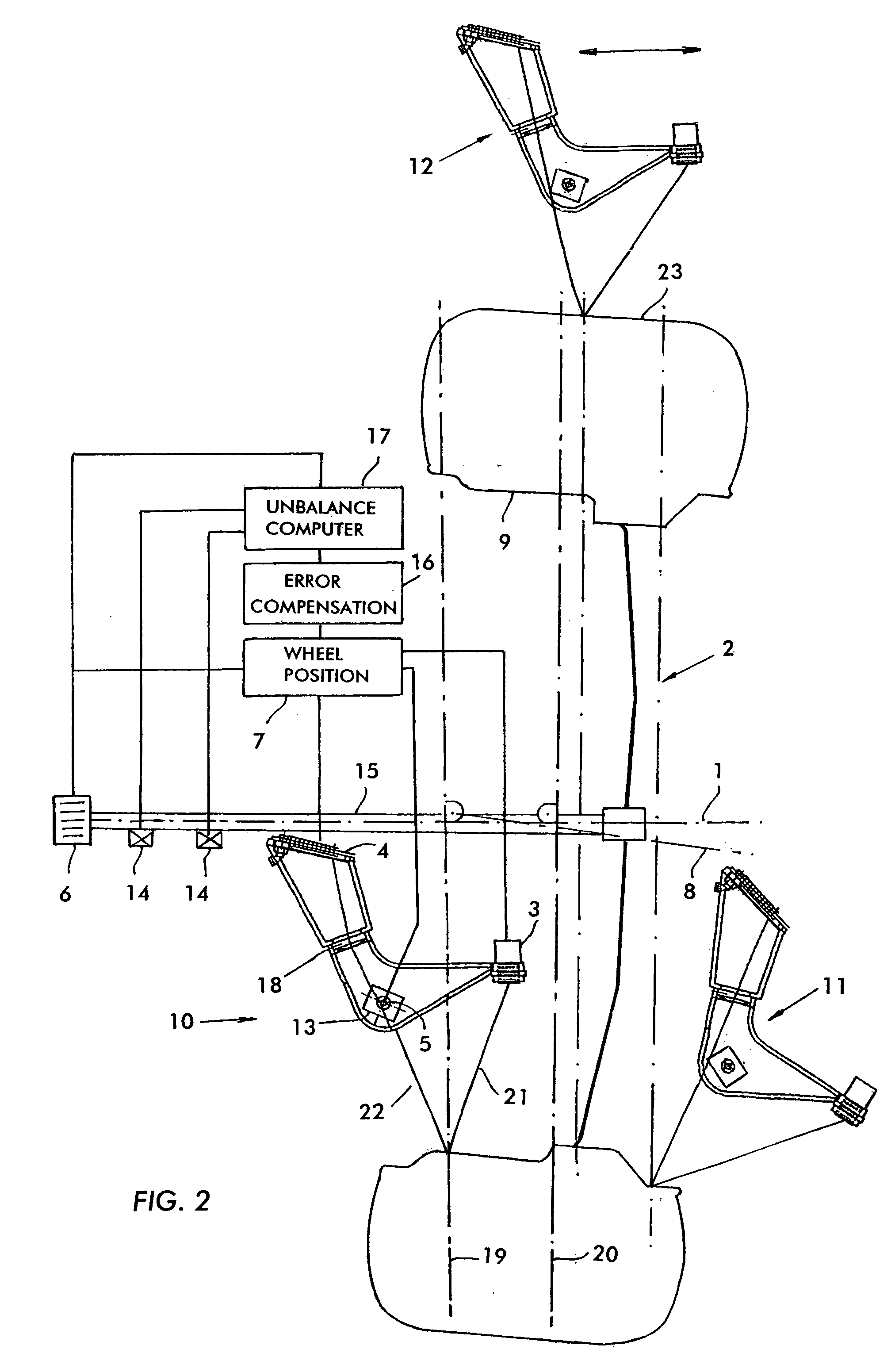
[0014]In the illustrated embodiments, a motor vehicle wheel 2 is fixed to a main shaft 15 which is supported rotatably about an axis of rotation 1 on the frame structure of a wheel balancing machine (not shown) in known manner, for example as is illustrated in WO 00 / 14503. In an unbalance measuring run the motor vehicle wheel 2 is rotated about the axis of rotation 1 and forces resulting from a wheel unbalance are measured by means of force measuring sensors 14 and evaluated in an unbalance evaluation device 17. In the evaluation procedure unbalance parameters are calculated in terms of balancing mass and rotary angle position. The balancing masses are then fixed in the form of balancing weights to the wheel in known manner at the calculated rotary angle positions to compensate for the wheel unbalance.

[0015]When the motor vehicle wheel 2 is fixed to the main shaft 15 by way of conventional clamping means, it frequently happens that the geometrical axis 8 of the wheel does not exactl...


PUM


Abstract

A method and an apparatus for determining geometrical data of a motor vehicle wheel 2 mounted rotatably about an axis of rotation 1, in which in at least two planes 19, 20 which are perpendicular to the axis of rotation 1, the distances of a plurality of measurement points on a respective periphery of the corresponding part of the wheel (wheel rim 9) from a reference location 5 and the rotary angle positions of the respective measurement points are measured and the position of the motor vehicle wheel 2 with respect to the axis of rotation 1 is determined from the measurement values.

Description

BACKGROUND OF THE INVENTION[0001]The invention concerns a method of determining geometrical data of a motor vehicle wheel mounted rotatably about an axis of rotation and an apparatus for carrying out that method.[0002]A method and an apparatus of that kind are known from EP 1 174 698 A2. In the known method and the known apparatus the motor vehicle wheel which can be fixed rotatably on the main shaft of a wheel balancing machine is scanned in a contactless mode, for example by means of a laser beam. The reflected beam is received by a position-sensitive receiver and the spacing of the scanned measurement points is measured. The spacings between a plurality of measurement points are used to determine the profile of the motor vehicle wheel, in terms of optimising the balancing operation.[0003]When fixing the motor vehicle wheel to a rotatable wheel mounting, for example the main shaft of a wheel balancing machine or to the rotatable wheel fixing of a motor vehicle wheel or another whe...

Claims


Application Information

Patent Timeline
Patent Type & Authority Patents(United States)
IPC IPC(8): G01C1/00G01B11/26G01B21/26G01M1/02G01M1/16G01M17/02
CPCG01M1/02
Inventor BRAGHIROLI, FRANCESCO
Owner SNAP ON EQUIP
Why Eureka
Try Eureka