Method and apparatus for thermal management of CT electronics

a technology of thermal management and electronics, applied in the field of computed tomography (ct) imaging systems, can solve the problems of difficult cooling of electronics, difficult direct convective cooling, and inability to meet the needs of the user, so as to reduce the inherent conductive coupling, reduce the local shielding of electronics, and achieve effective electronics cooling

Active Publication Date: 2006-06-20
GE MEDICAL SYST GLOBAL TECH CO LLC
View PDF4 Cites 35 Cited by
  • Summary
  • Abstract
  • Description
  • Claims
  • Application Information

AI Technical Summary

Benefits of technology

[0010]Yet a further advantage of the present invention is that use of thermoelectric coolers (TECs) removes the siting problems associated with placing an air to liquid type refrigeration system on the stationary side. Complete enclosure of the system means that EMI shielding is optimized and thus local shielding of the electronics can be reduced. The reduction in the local electronics shielding reduces the inherent conductive coupling between the electronics and the x-ray detector photo diode.
[0011]The present invention provides for using a heat exchanger to remove heat from the recirculated air. One embodiment of the present invention provides for using a combination of a heat sink and a thermoelectric cooler to remove heat from the recirculated air. This embodiment of the invention also provides for controller and a feedback control mechanism which is primarily responsible for determining the temperature of the recirculating air and regulating the thermoelectric cooler to keep the cooling air within a specified temperature range.
[0012]The present invention further provides effective electronics cooling while minimizing the temperature conductive coupling between the x-ray detector and the electronics. In one embodiment, the present invention provides for an array of heat pipes coupled to a spreader plate that is thermally linked to the heat generating chips. Heat is then piped away from the electronics and removed using forced convection. In yet another embodiment, the present invention provides for placement of heat pipes within the circuit boards. Yet another embodiment of the present invention provides for the use of heat pipes between the electronics packages.
[0013]The present invention further provides for use of wick type heat pipes being placed either horizontally or with the evaporator end radially further out than the condenser end such that rotational forces assist with heat flow through the heat pipe. In general, under rotating loads, a wick style heat pipe will function properly as long as the radial capillary pumping forces within the heat pipe are not exceeded by the rotational forces.
[0014]In situations where the rotational forces are exceeded by the capillary pumping forces, other heat conduction methods can be used. For example, the present invention provides for use of a combination of a wick type heat pipe and an axial groove thermal siphon, or wickless heat pipe. Axial groove heat pipes have enhanced performance under revolving conditions. This is mainly due to the axial groove functioning as an Archimedes screw under rotating conditions.
[0015]The present invention also provides for an axial groove heat pipe wherein the heat pipe is oriented such that the evaporator end is either parallel to or lower than the condenser end. Therefore, the liquid in the condenser end is not required to flow against gravity to cool the electronics when the gantry is tilted.

Problems solved by technology

Cooling of those electronics is made difficult for a number of reasons.
Also, very little space is available between the analog to digital converters, which makes direct convective cooling difficult, if not impractical.
Therefore, any thermal control solution must not only prevent the heat from the electronics from reaching the photodiode but prevent the possibility of over cooling the photodiodes.
There are two factors that make direct convective cooling difficult in a CT detector gantry.
The second factor hindering direct convective cooling is the fact that the electronics on a CT system rotate.
This rotation tends to cause a decrease in airflow rate through any cooling fans that may be attached to the rotating side due to changes in the fan inlet flow boundary conditions.
The rotation of the gantry also tends to cause mixing of the air inside the gantry thereby leading to a nearly instantaneous step change in the cooling air temperature.
Thus, direct convection cooling has a negative impact on electromagnetic interference (EMI) shielding.

Method used


Image

  • Method and apparatus for thermal management of CT electronics
  • Method and apparatus for thermal management of CT electronics
  • Method and apparatus for thermal management of CT electronics

Examples


Embodiment Construction

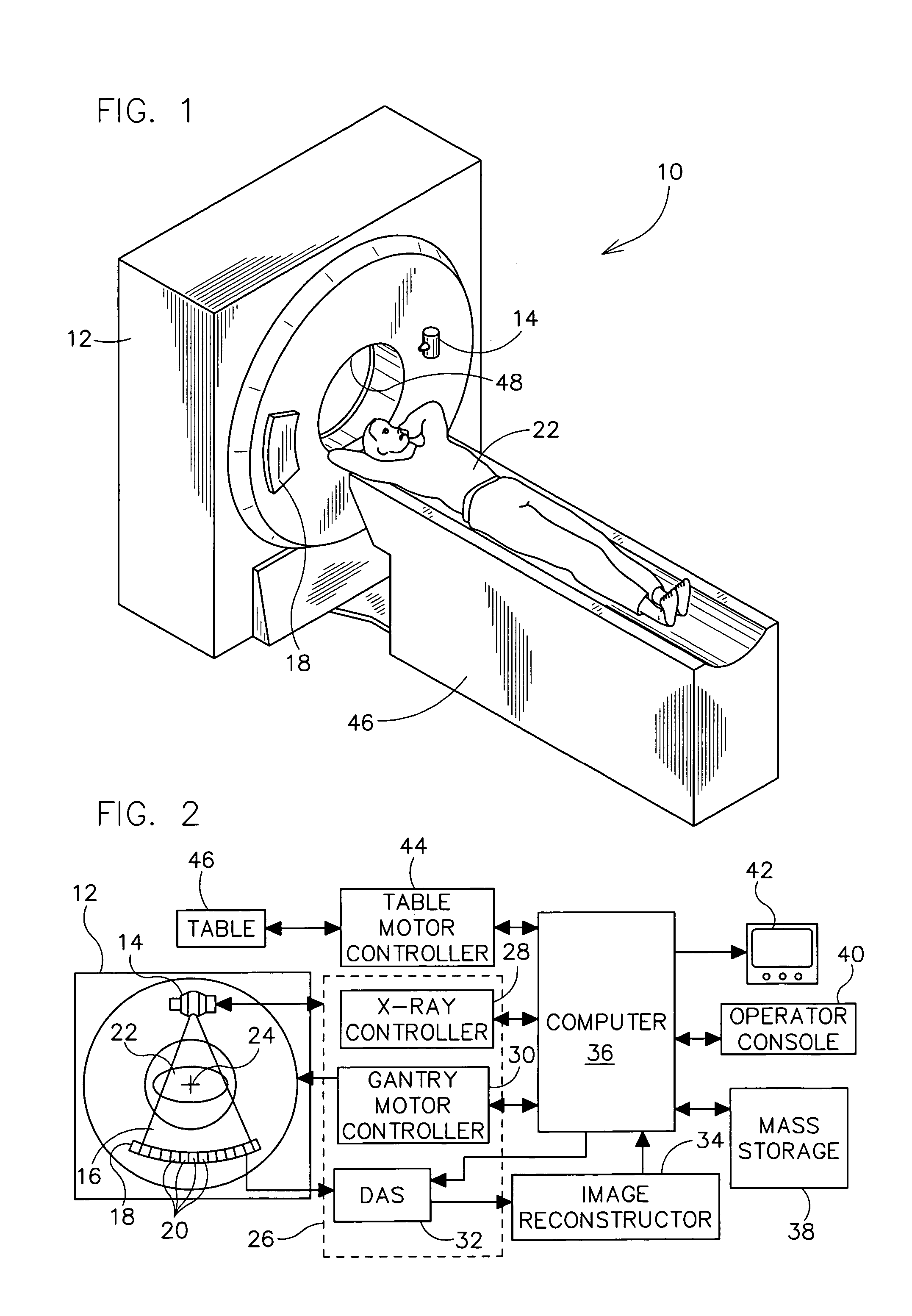
[0032]Referring now to the drawings in detail wherein like-numbered elements correspond to like elements throughout, FIGS. 1 and 2 show a multi-slice scanning computed tomography (CT) imaging system 10. The CT imaging system 10 is shown as including a gantry 12 representative of a “third generation” CT imaging system. Gantry 12 has an X-ray source 14 that projects a beam of X-rays 16 toward a detector array 18 on the opposite side of gantry 12. Detector array 18 is formed by a plurality of detector rows (not shown) including a plurality of detector elements 20 which together sense the projected X-rays that pass through an object, such as a medical patient 22. Each detector element 20 produces an electrical signal that represents the intensity of an impinging X-ray beam and hence the attenuation of the beam as it passes through object or patient 22. During a scan to acquire X-ray projection data, gantry 12 and the components mounted thereon rotate about a center of rotation 24. FIG. ...


PUM


Abstract

The present invention discloses a method and apparatus for cooling the electronics associated with Computed Tomography (CT) detector arrays. More particularly, the present invention discloses use of thermoelectric coolers in cooling CT detector electronics. The present invention also provides for using blowers or fans to recirculated air within a plenum for the cooling of CT detector electronics. The present invention also discloses the use of wick type heat pipes being placed either horizontally or with the evaporator end radially farther out than the condenser end such that rotational forces assist with heat flow through the heat pipe for cooling CT detector electronics. The present invention also discloses use of axial groove heat pipes to cool the CT detector electronics because they have enhanced performance under revolving conditions. Lastly, the present invention discloses use of heat sinks and circulation fans in combination with either type of heat pipe.

Description

BACKGROUND OF THE INVENTION[0001]The present invention relates generally to computed tomography (CT) imaging systems. More particularly, it relates to a method and apparatus for cooling the electronics associated with CT scanners.[0002]In at least some CT imaging system configurations, a stationary floor-mounted frame includes an x-ray source and a radiation detector array. The x-ray source projects a fan-shaped beam that is collimated to lie within an X-Y plane of a Cartesian coordinate system and is generally referred to as the “imaging plane”. The x-ray beam passes through the object being imaged, such as a patient. The beam, after being attenuated by the object, impinges upon the array of radiation detectors. The intensity of the attenuated beam radiation received at the detector array is dependent upon the attenuation of the x-ray beam of the object. Each detector element of the array produces a separate electrical signal that is a measurement of the beam attenuation at the det...

Claims


Application Information

Patent Timeline
Patent Type & Authority Patents(United States)
IPC IPC(8): A61B6/12A61B6/03
CPCA61B6/4488A61B6/035
Inventor LACEY, JOSEPH J.JOSHI, ASHUTOSH
Owner GE MEDICAL SYST GLOBAL TECH CO LLC
Why Eureka
Try Eureka