
Electric hopper spreader

a technology of electric hoppers and spreaders, which is applied in the direction of self-acting watering devices, ways, constructions, etc., can solve the problems of limited amperage available for use by these motors, and achieve the effects of less output, less power draw of conveyor drives, and more efficient power transfer systems

Inactive Publication Date: 2006-06-27
AIR FLO
View PDF16 Cites 10 Cited by
  • Summary
  • Abstract
  • Description
  • Claims
  • Application Information

AI Technical Summary

Benefits of technology

"The present invention is a material spreading system for a truck that uses less power from the vehicle's battery. The system includes a conveyor and a spinner, both powered by electric motors. The conveyor has a high-efficiency gearbox or chain and sprocket system that translates most of the power it receives into useful output. This allows the conveyor to operate at faster speeds and with greater precision. The spinner can also be fully powered by its own dedicated electric motor, which allows for independent control of the spinner and conveyor. This results in more precise spreading of the hopper contents."

Problems solved by technology

Since both electric motors are powered off the vehicle's battery there is limited amperage available for use by these motors.

Method used


Image

  • Electric hopper spreader
  • Electric hopper spreader

Examples


Embodiment Construction

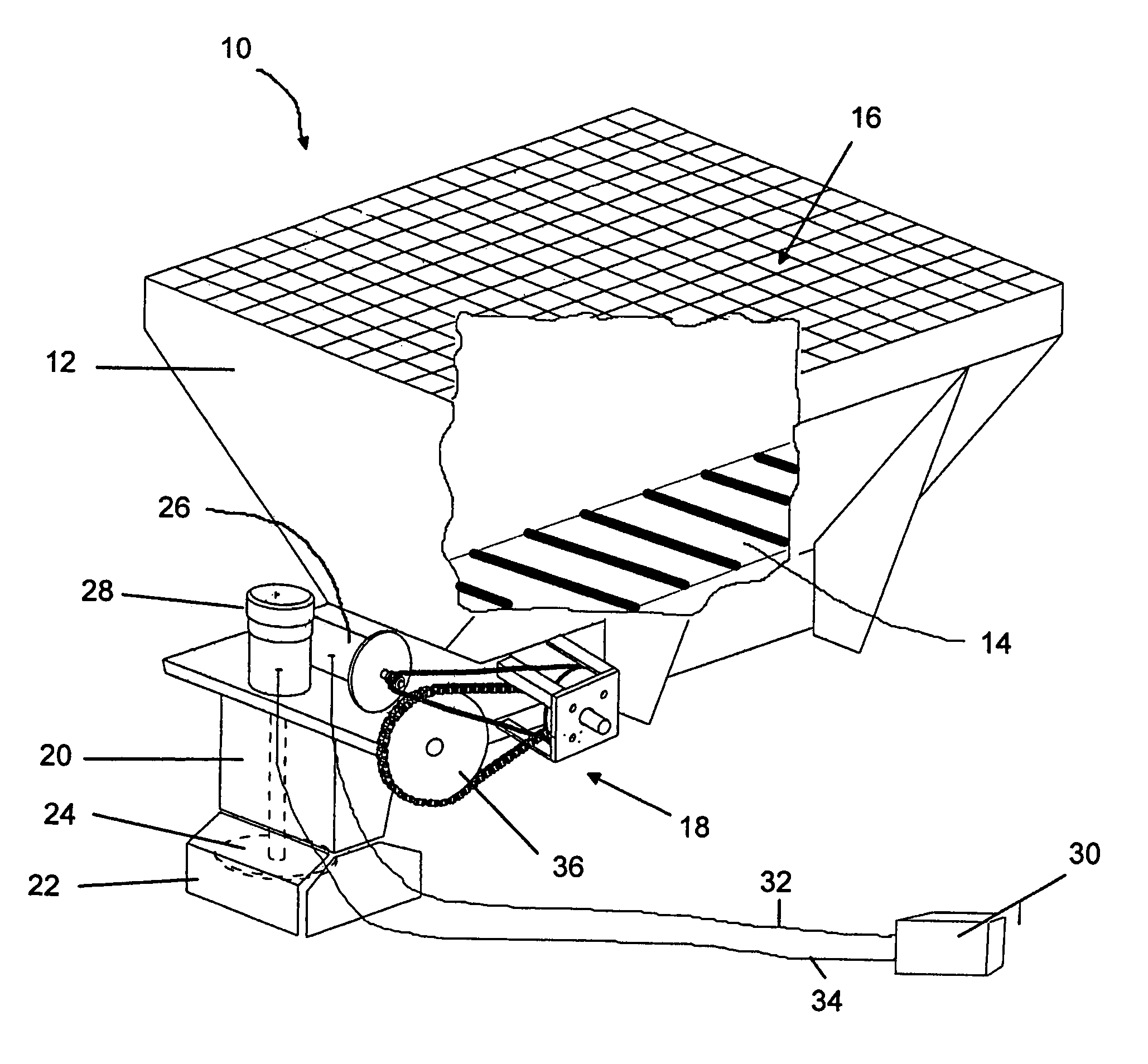
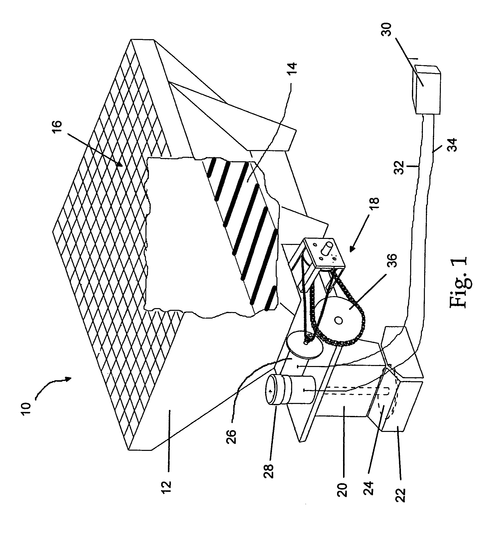
[0016]Referring now to the FIGURE wherein like numerals refer to like parts throughout, there is seen in FIG. 1 a hopper spreader 10 according to the present invention that can be placed in the bed of a pick-up truck or similar vehicle and used to spread materials, such as road salt, rearwardly from the vehicle. Hopper spreader 10 comprises a hopper 12 having a conveyor 14, such as a conveyor chain or belt, positioned in the bottom of hopper cavity 16 and driven by a conveyor drive system 18, a vertical spreader housing 20 communicating with hopper 12 and having a skirt 22, a spinner 24 positioned inside skirt 22 of housing 20, and two separate electric motors, conveyor motor 26 and spinner motor 28, interconnected to conveyor drive system 18 and spinner 24, respectively. Conveyor motor 26 and spinner motor 28 are both powered by the electrical system of the vehicle 30 by leads 32 and 34, respectively.

[0017]Conveyor drive system 18 includes a chain and sprocket driver 36 for transla...


PUM


Abstract

A material spreading drive system for a hopper spreader having a conveyor and a spreader separately driven by two electric motors that are powered directly from the electrical system of the vehicle. The conveyor drive system includes a gearbox that transmits 90 to 95 percent of power received from the conveyor motor to the conveyor, thus reducing the demand on the electrical system. As a result, the electrical system is capable of also powering a second electric motor that drives the spreader. Due to the improved efficiency of the conveyor belt system, increased conveying and spreading speed are possible as well as independent control over the operating speeds of the conveyor and spreader.

Description

BACKGROUND OF THE INVENTION[0001]1. Field of Invention[0002]The present invention relates to conveyor drive spreaders and, more specifically, to spreaders having a spinner and conveyor powered by separate motors.[0003]2. Description of Prior Art[0004]Conventional drive systems for a material spreading system on a vehicle, such as a hopper spreader, include an auxiliary source for powering both the conveyor drive system and the associated spreading spinner system. The auxiliary source may be a separate internal combustion engine, a hydraulic system with pump, valves and reservoir powered by the truck's engine, or an electric motor that is powered by the electrical system of the vehicle. Electrically powered spreaders are advantageous because they eliminate the need for a separate high maintenance auxiliary engine to power the spreader or the expense of attaching a separate hydraulic system to power the spreader hydraulically.[0005]Conventional electrically powered spreaders were deve...

Claims


Application Information

Patent Timeline
Patent Type & Authority Patents(United States)
IPC IPC(8): B05B3/00A01C19/00A01G27/00E01C19/20
CPCE01C19/202E01C19/203E01C2019/2075
Inventor MUSSO, CHARLES S.MUSSO, TOM
Owner AIR FLO
Learn More