System for controlling a moving part, steering system for a light vehicle and tricycle fitted with said system

a technology of steering system and moving part, which is applied in the direction of bicycles, motorcycles, unicycles, etc., can solve the problems of reducing the reliability difficult to actuate the propulsion of the control bar, and the user's reflexes cannot be relied on to take deliberate action on the appropriate grip to recover the situation. , to achieve the effect of convenient driving a lightweight vehicl

Inactive Publication Date: 2006-06-27
SPORT SYST ENG
View PDF12 Cites 8 Cited by
  • Summary
  • Abstract
  • Description
  • Claims
  • Application Information

AI Technical Summary

Benefits of technology

[0007]Consequently, a first object of the invention is a cable control system for a mobile part of a device composed of two separate pivoting handles each fixed to the first end of a first cable, the second end of one of the two first cables being fixed to one side of the steering shaft and the second end of the other of the two first cables being fixed to the other side of the steering shaft, to control the orientation of the mobile part by pivoting a side handle, in order to apply tension in the corresponding cable among the first two cables and make the mobile part move.
[0008]According to the invention, it comprises a second cable, one end of which is fixed to a first side handle, opposite to the first end of the corresponding first cable and the second end of which is fixed to the second side handle, opposite to the first end of the first corresponding cable. This arrangement slaves the two handles to each other. In this way, an operator action on one of the handles will cause a corresponding movement on the other handle, even if the operator does not act on the second handle. It can easily be understood that this makes it easier to drive a lightweight vehicle. Furthermore, in case of danger or an accident situation, a reflex action by the operator on either of the two handles will control the steering system, regardless of which handle is used.
[0011]two separate pivoting side handles each fixed to the first end of a first cable, the second ends of each of the two first cables being fixed to each side of the steering shaft, to control the orientation of the steering wheel by pivoting a side handle, in order to create tension in the corresponding cable among the two first cables and to cause rotation of the steering shaft.
[0012]According to the invention, it comprises a second cable, the first end of which is fixed to a first side handle, opposite the first end of the first corresponding cable and for which the second end is fixed to the second side handle opposite the first end of the corresponding first cable. This arrangement slaves the two handles to each other. In this way, an operator action on one of the handles will cause a corresponding movement on the other handle, even if the operator does not act on the second handle. It can easily be understood that this makes it easier to drive a lightweight vehicle. Furthermore, in case of danger or an accident situation, a reflex action by the operator on either of the two handles will control the steering system, regardless of which handle is used.
[0019]It is advantageous if a sheath is used around each of the cables.

Problems solved by technology

This reduces the reliability of these control bars and is not ergonomic.
Furthermore, it is difficult to actuate these control bars for propulsion at the same time as offsetting them to steer the tricycle, particularly if it is intended to go around turns with a small radius of curvature.
One of the disadvantages of this situation is that in case of danger, the user's reflexes cannot be relied on to take deliberate action on the appropriate grip to recover the situation.

Method used


Image

  • System for controlling a moving part, steering system for a light vehicle and tricycle fitted with said system
  • System for controlling a moving part, steering system for a light vehicle and tricycle fitted with said system
  • System for controlling a moving part, steering system for a light vehicle and tricycle fitted with said system

Examples


Embodiment Construction

[0026]The control system according to the invention is described in its application to a tricycle.

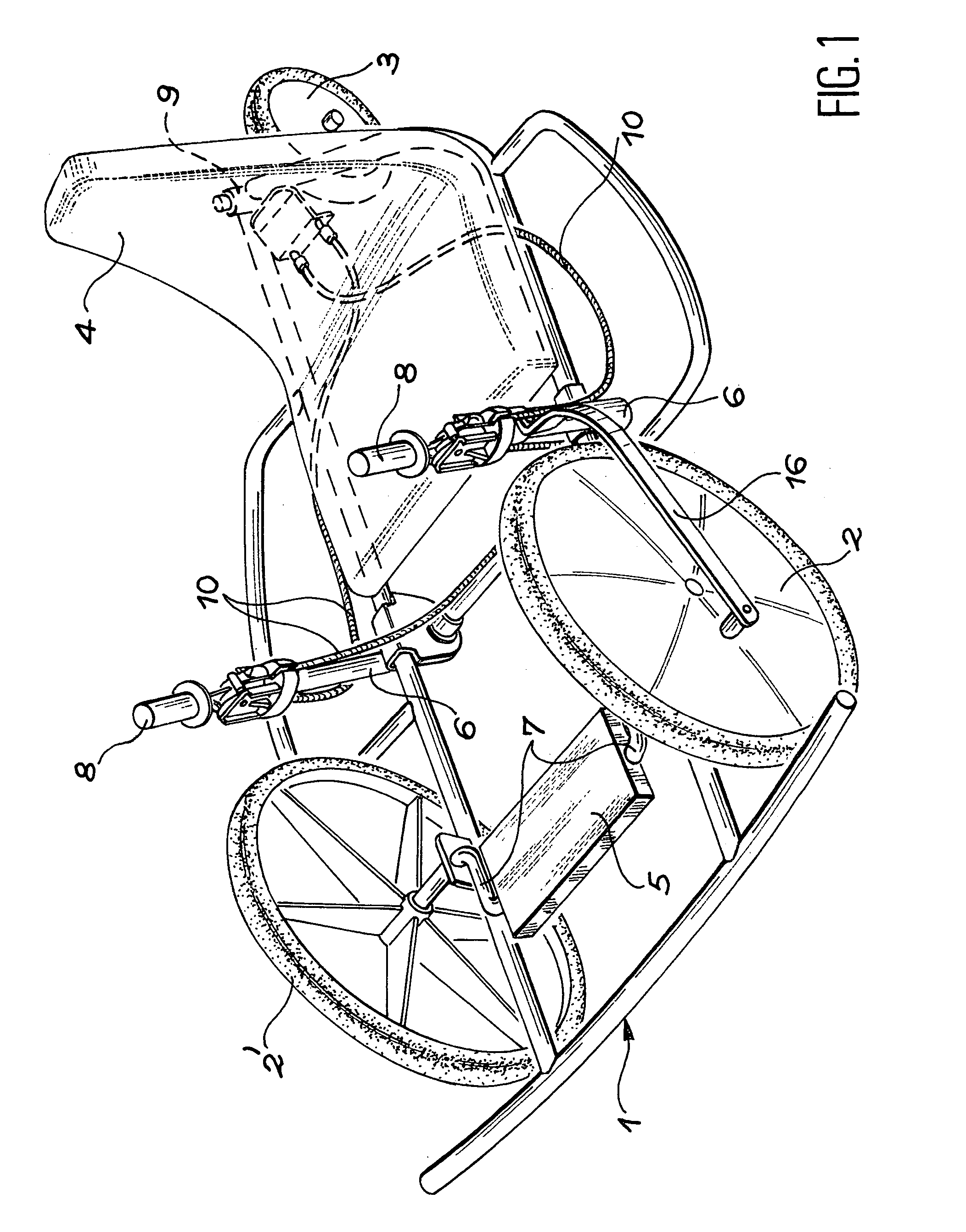
[0027]FIG. 1 shows an asymmetric view of a tricycle according to the invention, in other words equipped with a steering system according to the invention.

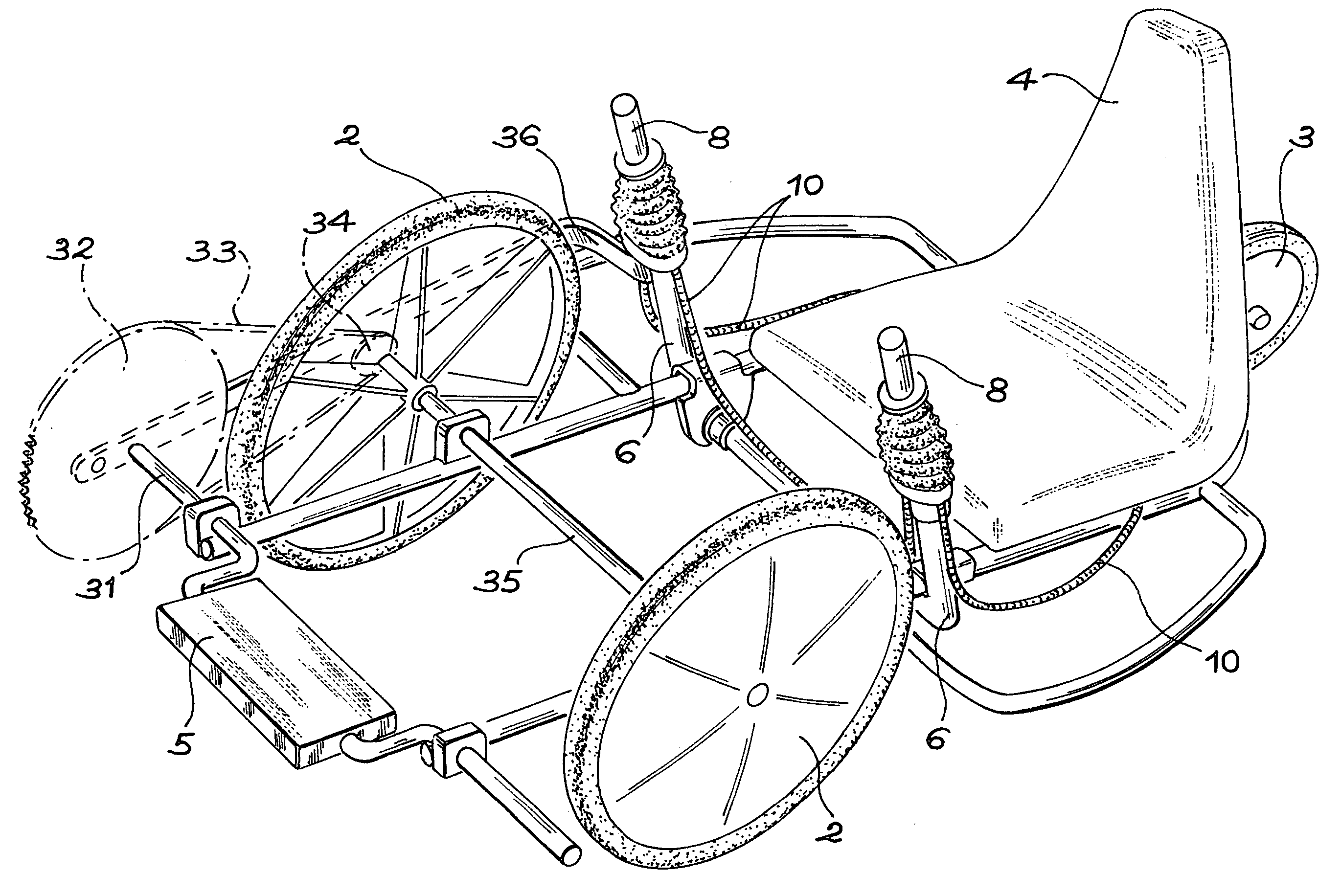
[0028]It includes mainly a frame 1, a driving wheel 2 and a free wheel 2′ that in this case are two front wheels, and one rear wheel 3 that is a steering wheel. It would be possible to use two driving wheels with a differential. A seat is mounted on frame 1, at the rear steering wheel 3.

[0029]The tricycle is propelled by the combined efforts made by a driver on the seat 4 pedalling on a single propulsion pedal 5 and actuating two side propulsion arms 6.

[0030]Since the propulsion pedal 5 is central and there is only one, the driver's feet and legs produce a combined movement. The same is true for the driver's arms, since the propulsion arms 6 of the tricycle are coupled in a synchronised manner and in phase. This type of propulsion is v...


PUM


Abstract

The steering system according to the invention provides a means of coordinating the movements of the two steering handles on a machine such as light tricycle type vehicles propelled by a pedal (5) and propulsion arms (6).The steering system comprises two handles (8) installed free to pivot, each handle being installed at the end of one of the propulsion arms (6) and a first cable (10) being fixed to the bottom of each handle. The second end is fixed to the steering shaft (9) of the tricycle. A second cable connects the two handles to each other to coordinate the movement of the handles (8).Application to leisure tricycles, light vehicles in general, indoor sports and medical re-education apparatus and static game facilities for leisure parks.

Description

FIELD OF THE INVENTION[0001]The invention relates to a cable control system that can be used on a steering system for a light vehicle (tricycle, quadricycle, bicycle, water sports equipment, snowmobile) or on a behavioural control system for a fixed product (indoor sports, medical re-education, static game products for leisure parks).PRIOR ART AND PROBLEM THAT ARISES[0002]French patent No. 2 659 742 assigned to this applicant describes a tricycle equipped with a propulsion system to create a rotary movement by a combined action of a driver's hands and legs. The tricycle described in this document includes a seat arranged in the middle of the tricycle, on which the driver sits in a semi-lying position. A drive shaft is arranged on a frame and is driven in rotation by two drive cranks at the ends of the frame. Two pedals mounted on the control cranks on each side of the ends of the shaft enable the driver to press them in phase. Two control bars, or propulsion arms, are installed free...

Claims


Application Information

Patent Timeline
Patent Type & Authority Patents(United States)
IPC IPC(8): B62K5/04B62M1/12B62K5/05B62K21/00B62K21/12B62M1/06B62M9/00
CPCB62K3/005B62K5/05B62M1/12B62K21/12B62K21/00
Inventor BRICHET, RODOLPHEBONNEAU, OLIVIER
Owner SPORT SYST ENG
Why Eureka
Try Eureka