Non-conductive extension pole

a non-conductive, extension pole technology, applied in the direction of rod connection, electric discharge tube/lamp manufacture, hoisting equipment, etc., can solve the problem of increasing the risk of operator injury due to electrical shock, the limitation of providing a maximum extended reach of only twice the retracted length of the pole, and the inconvenient handling and/or storage of conventional two-section extension poles having a long reach. problem, to achieve the effect of reducing the risk of electrical shock

Active Publication Date: 2006-06-27
SPECIALTY PROD OF GREENWOOD MISSOURI
View PDF19 Cites 21 Cited by
  • Summary
  • Abstract
  • Description
  • Claims
  • Application Information

AI Technical Summary

Benefits of technology

[0008]A still further object of the present invention is to provide an extendable bulb-changing device that is made entirely of non-conductive materials to thereby minimize the risk of electrical injury to the operator.

Problems solved by technology

Conventional extendable bulb-changing devices employing only two telescoping sections have the limitation of providing a maximum extended reach of only twice the retracted length of the pole.
Thus, conventional two-section extension poles having a long reach may be inconvenient to handle and / or store in the retracted position because of their excessive retracted length.
Finally, constructing an extendable light bulb changing apparatus out of an electrically conductive material increases the risk of operator injury due to electrical shock.

Method used


Image

  • Non-conductive extension pole
  • Non-conductive extension pole
  • Non-conductive extension pole

Examples


Embodiment Construction

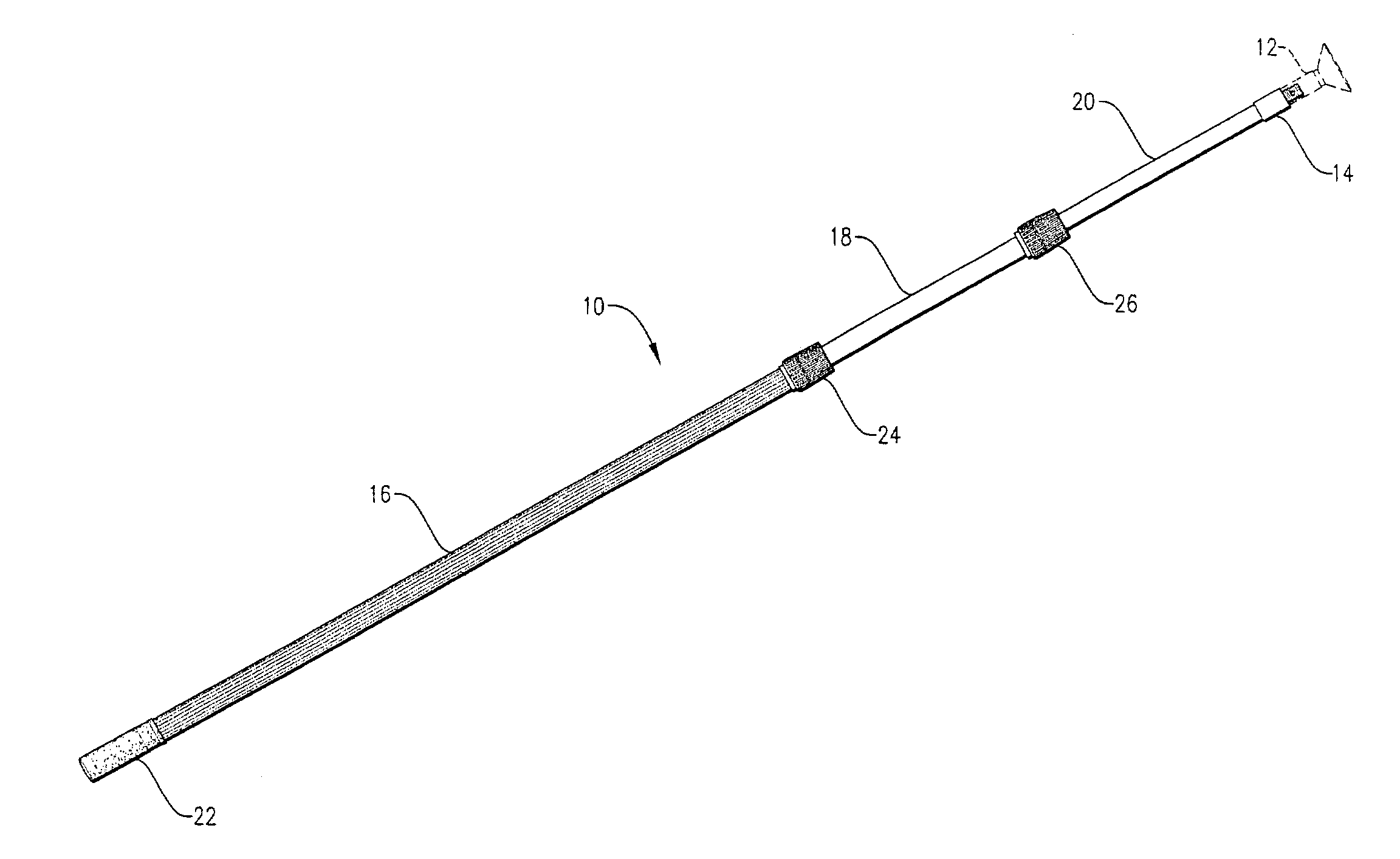
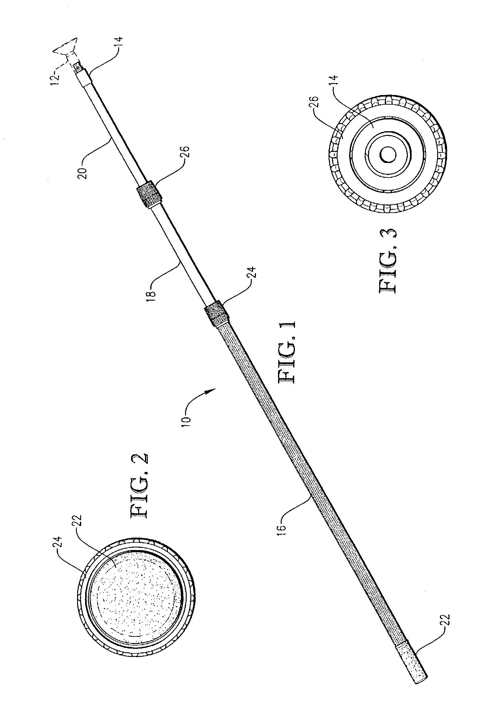
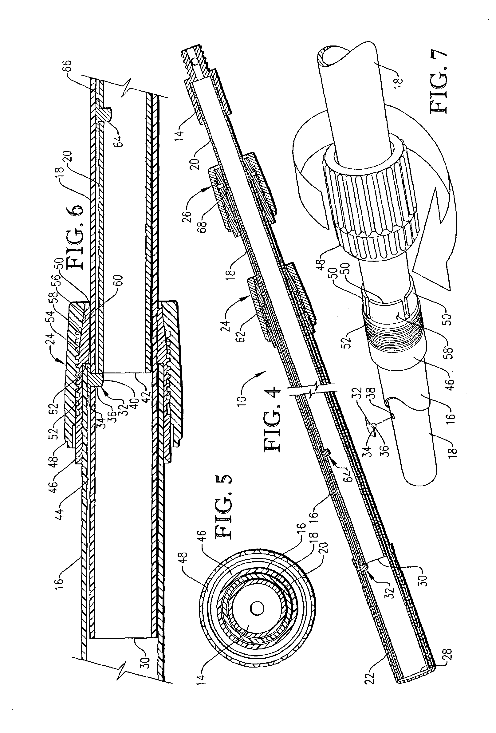
[0021]Referring initially to FIGS. 1–3, extension pole 10 is illustrated in a partially extended position with a bulb-gripping device 12 (shown in phantom lines) coupled to a normally-upper end of pole 10 via a connector 14. It is preferred for bulb-gripping device 12 to be constructed in accordance with the description provided in U.S. Pat. No. 5,148,723, issued Sep. 22, 1992, the entire disclosure of which is incorporated herein by reference. Extension pole 10 generally comprises a first section 16, a second section 18, and a third section 20. First, second, and third sections 16,18,20 are telescopically intercoupled with second section 18 being at least partly received in first section 16 and third section 20 being at least partly received in second section 18. Extension pole 10 can be retracted and extended by sliding second section 18 into and out of first section 16 and third section 20 into and out of second section 18. Extension pole 10 further includes a hand grip 22 couple...


PUM


Abstract

An extension pole suitable for use in light bulb changing operations. The extension pole comprises first, second, and third telescopically intercoupled sections. A first locking assembly selectively locks the first and second sections to one another, and a second locking assembly selectively locks the second and third section to one another. The extension pole is made entirely of non-conductive materials to thereby reduce the risk of electrical shock to the operator.

Description

BACKGROUND OF INVENTION[0001]1. Field of the Invention[0002]The present invention relates generally to extendable poles that can be used to change light bulbs. In another aspect, the invention concerns a three-section, non-conductive, extension pole with a bulb-gripping device coupled to an end of the pole.[0003]2. Discussion of Prior Art[0004]Extension poles with bulb-gripping devices have been used for years to change light bulbs in hard-to-reach locations such as, for example, recessed light fixtures in vaulted ceilings. Most conventional extendable bulb-changing devices include two elongated, telescoping sections with a bulb-gripping device attached to the end of one section. Conventional extension poles used for changing light bulbs typically employ a pin-type locking mechanism for selectively inhibiting relative telescopic sliding of the two sections. Further, the telescoping sections of many conventional extendable bulb-changing devices are composed of an electrically conduct...

Claims


Application Information

Patent Timeline
Patent Type & Authority Patents(United States)
IPC IPC(8): F16B7/10F16B7/14H01J9/00H01K3/32
CPCF16B7/149H01J9/003H01K3/32Y10T403/7077Y10T403/7083
Inventor NEWMAN, ROBERT D.GUITTAR, BUFORD J.
Owner SPECIALTY PROD OF GREENWOOD MISSOURI
Why Eureka
Try Eureka