LED lamp

Active Publication Date: 2006-06-27
CITIZEN ELECTRONICS CO LTD
View PDF6 Cites 129 Cited by
  • Summary
  • Abstract
  • Description
  • Claims
  • Application Information

AI Technical Summary

Benefits of technology

[0008]It is, therefore, an object of the present invention to provide an LED lamp mountable as a flash light source of a camera provided in a small

Problems solved by technology

The xenon tube has been unsuitable for an instrument such as a mobile phone whose miniaturization and low power consumption are requested, because the xenon tube has strong light, and high power consu

Method used


Image

  • LED lamp
  • LED lamp
  • LED lamp

Examples


first embodiment

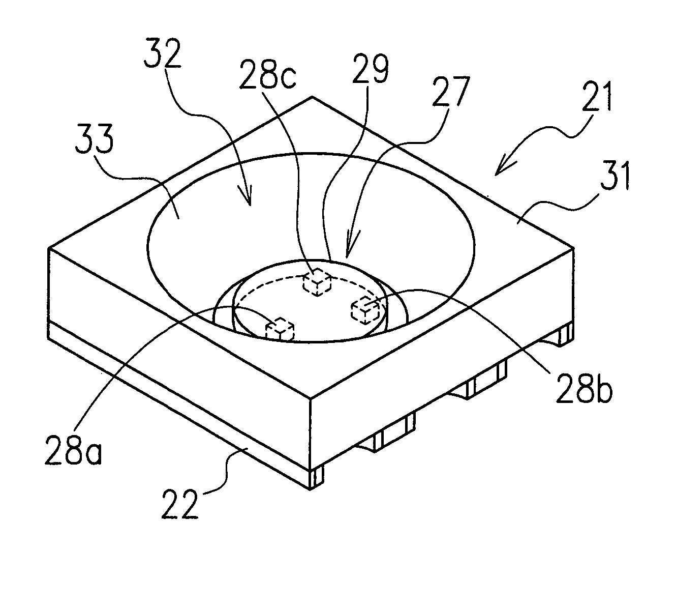
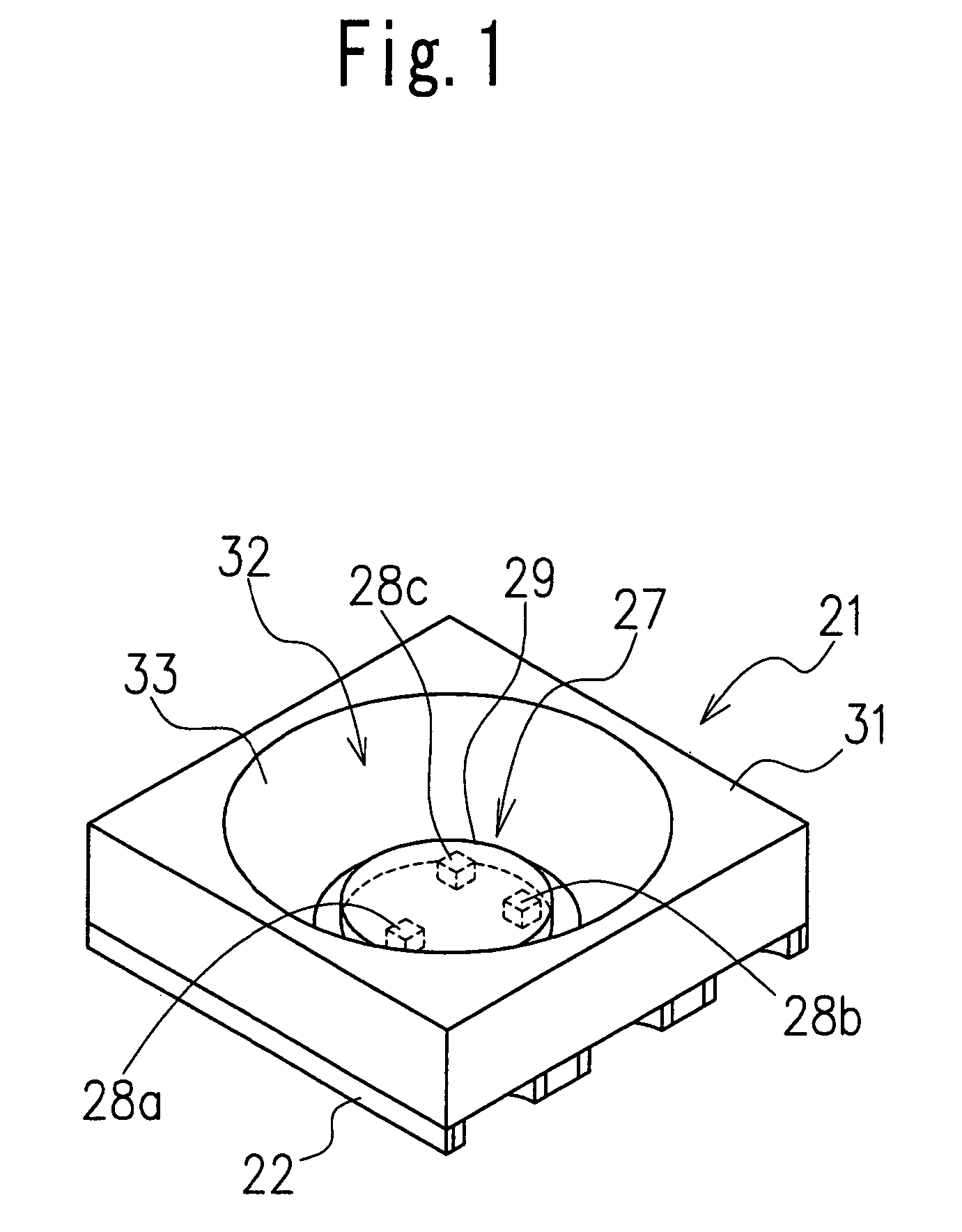
[0029]FIGS. 1 to 4 illustrate the LED lamp 21 according to the present invention.

[0030]The LED lamp 21 comprises a circuit substrate 22, a light emitting unit 27 mounted on the circuit substrate 22 and a reflecting frame 31 mounted on the circuit substrate 22 to surround the light emitting unit 27.

[0031]The circuit substrate 22 is formed with three pairs of anode and cathode electrodes, for example. More specifically, the circuit substrate 22 has a generally rectangular shape made of glass epoxy or BT resin or the like, and the anode and cathode electrodes A1, A2, A3, and K1, K2, K3 are formed on both side surfaces of the circuit substrate by through holes, as shown in FIG. 3. In addition, three light emitting diode elements which will be explained hereinafter, or LED elements 28a, 28b and 28c are mounted between leading ends of each of a pair of anode and cathode electrodes A1 and K1, a pair of anode and cathode electrodes A2 and K2, and a pair of anode and cathode electrodes A3 an...

second embodiment

[0037]FIGS. 5 and 6 illustrate the LED lamp according to the present invention.

[0038]In FIGS. 5 and 6, the same reference numerals are attached to the same parts as these in the first embodiment shown in FIGS. 1 to 4.

[0039]A LED lamp 41 in the embodiment is composed of the circuit substrate 22 provided with an electrode pattern, the light emitting unit 27 mounted on the circuit substrate 22, the reflecting frame 31 having the reflecting surface 33 in the concave portion 32, surrounding the light emitting unit 27, an air layer 40 surrounded by the reflecting frame 31 and positioned above the light emitting unit 27, and a lens body 44 provided on the reflecting frame 31 so that the air layer 40 is disposed between the lens body 44 and the light emitting unit 27. The lens body 44 includes a convex surface 46 provided at an upper surface thereof. Although a light collecting operation by the light emitting unit 27 and the reflecting frame 31 is the same as in the LED lamp 21 in the first...


PUM


Abstract

An LED lamp including a circuit substrate (22) on which an electrode pattern is formed, a reflecting frame (31) including a tapered concave portion (32) having an inner peripheral surface broadening toward an upper end of the reflecting frame, a light emitting unit (27) disposed on a central portion of the concave portion (32), an air layer (40) disposed above the light emitting unit (27), and a lens body (44) provided through the air layer above the reflecting frame (31), the reflecting frame being provided with an air hole (45) for communicating the air layer with an outside area of the LED lamp.

Description

BACKGROUND OF THE INVENTION[0001]1. Field of the Invention[0002]The present invention relates to an LED lamp mounted on a mobile phone having a function for a camera, a mobile information terminal device or the like, and used as a flash light source.[0003]2. Description of Related Art[0004]Generally, a flash light source has been mounted on a camera, and a xenon tube has been used for a great number of flash light sources. The xenon tube has been unsuitable for an instrument such as a mobile phone whose miniaturization and low power consumption are requested, because the xenon tube has strong light, and high power consumption.[0005]Therefore, a small surface-mountable LED lamp in which a plurality of light emitting elements are arranged on a chip substrate is used practically as shown in CL-460S, 470S series, data sheet, [on line], Citizen Electronics Co., Ltd, Feb. 20, 2003 searching, Internet URL<http: / www.c-e.co.jp / products / index1.htm1>.[0006]By using the LED lamp having su...

Claims


Application Information

Patent Timeline
IPC IPC(8): F21S6/00F21S2/00H01L25/075H01L33/50H01L33/56H01L33/58H01L33/60
CPCH01L33/486H01L25/0753H01L33/58H01L2924/0002H01L2924/00F21K9/60F21Y2115/10
Inventor OMATA, KAZUKI
Owner CITIZEN ELECTRONICS CO LTD
Why Eureka
Try Eureka