Connector

a technology of electrical connectors and connectors, applied in the direction of electrically conductive connections, electrical discharge lamps, coupling device connections, etc., can solve the problems of inconvenient connection, inability to secure and release, and danger of current light sockets, so as to facilitate the connection of bulbs

Inactive Publication Date: 2006-06-27
MCLEISH GRAHAM JOHN
View PDF10 Cites 181 Cited by
  • Summary
  • Abstract
  • Description
  • Claims
  • Application Information

AI Technical Summary

Benefits of technology

[0041]Alternatively one part of the connector may further comprise a standard bulb fitting at one end, such as a screw or bayonet, so that a bulb can be placed in t...

Problems solved by technology

Although these connectors are generally competent, they can be difficult to secure and release, particularly in out of reach places such as sockets suspended from the ceiling.
Moreover, some current light sockets are hazardous because they cont...

Method used


Image

  • Connector
  • Connector
  • Connector

Examples


Embodiment Construction

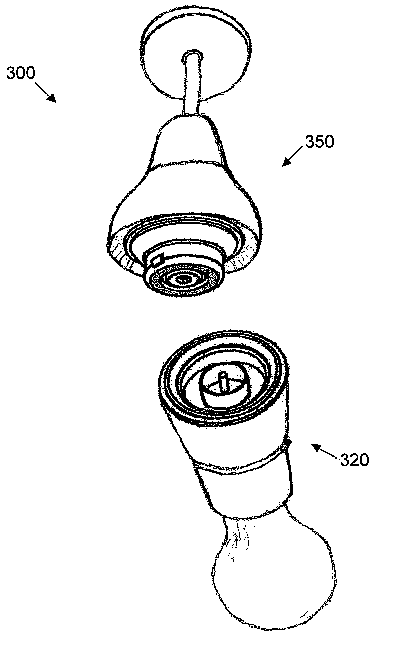
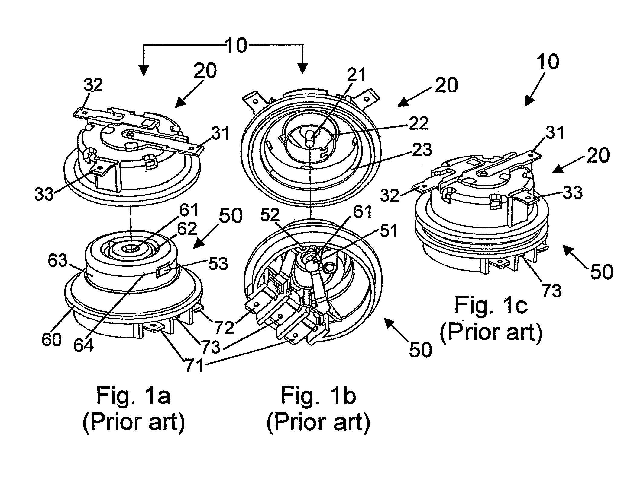
[0095]A known connector 10 is shown in FIGS. 1a–1c and is disclosed in more detail in U.S. Pat. No. 5,971,810 the disclosure of which is incorporated herein by reference. The connector 10 comprises a male part 20 adapted to mate and form an electrical connection with a female part 50. The male part 20 comprises a live central pin terminal 21, and first neutral 22 and second earth 23 annular terminals. The female part comprises a boss 63 which projects from a body 60 of the female part 50, a central aperture 61 for receiving the pin terminal 21 and an annular recess 62 for receiving the annular terminal 22 of the male part 20. When connected, as shown in FIG. 1c, the second annular terminal 23 of the male part 20 locates around the boss 63 and live and neutral female terminals 51, 52 are located within the central aperture 61 and annular recess 62 respectively for electrical connection with the corresponding male terminals 21, 22. An earth terminal 53 is provided through a side wall ...


PUM


Abstract

An electrical connector (100) comprising a male (120) and female (150) part, each part (120, 150) having a magnet (135, 165) adapted to attract the parts (120, 150) together to make a connection. The parts (120, 150) can connect at any relative rotational orientation and preferred embodiments prevent offset connection between the magnets (135, 165) or parts (120, 150). The connector (100) is particularly suited for use in out of reach locations, for example to easily and safely replace light bulbs into sockets suspended from a ceiling.

Description

TECHNICAL FIELD[0001]This invention relates to an electrical connector, particularly but not exclusively for use in difficult to and / or out of reach locations.BACKGROUND[0002]Electrical connectors are used in a variety of domestic and industrial Applications. A number of different connectors are known and these vary from application to application, a 3-pin plug and wall socket is a typical example.[0003]There are two popular types of connector for connecting light bulbs to a socket; a thread connection and a bayonet connection. For the thread connection, the bulb thread is rotationally aligned with a thread of the socket and then screwed into the socket allowing respective electric terminals on the bulb and socket to connect.[0004]The bayonet connection has pins which extend radially from the bulb. The pins are aligned with apertures in a circumferentially extending rim of the socket and inserted therethrough against action of a spring in the socket and so to allow respective termin...

Claims


Application Information

Patent Timeline
IPC IPC(8): H01R11/30H01R13/62H01R24/38H01R33/20
CPCH01R13/6205H01R33/20H01R24/38H01R2103/00
Inventor MCLEISH, GRAHAM JOHN
Owner MCLEISH GRAHAM JOHN
Why Eureka
Try Eureka