Injection devices

a technology of injection device and injection needle, which is applied in the direction of intravenous device, infusion needle, infusion syringe, etc., can solve the problems of too expensive simply to throw away, complicated firing device,

Inactive Publication Date: 2006-06-27
OWEN MUMFORD
View PDF11 Cites 113 Cited by
  • Summary
  • Abstract
  • Description
  • Claims
  • Application Information

AI Technical Summary

Benefits of technology

[0010]Generally, there will also be a separately moulded protective cap to fit over the forward end of the completed body. This cap is conveniently adapted to co-operate with the trigger to prevent that being operated while the cap is on. The cap can also have an internal formation that projects into the barrel to co-operate with a sheath initially provided over the needle of the capsule, removal of the cap causing the sheath to be pulled off the needle.

Problems solved by technology

Hitherto, these firing devices have been quite complicated and expensive, and it is necessary to load and unload the syringe before and after use and to keep the device itself for repeated use.
It is too expensive simply to throw away.
Also there have been problems with ensuring that the return spring works properly.

Method used


Image

  • Injection devices
  • Injection devices
  • Injection devices

Examples


Embodiment Construction

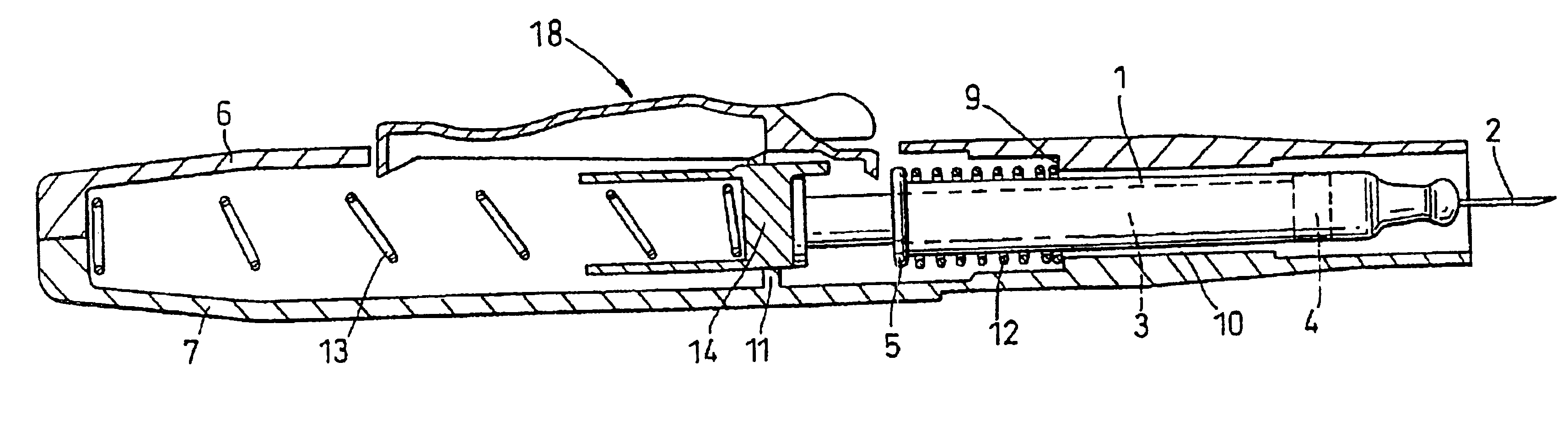
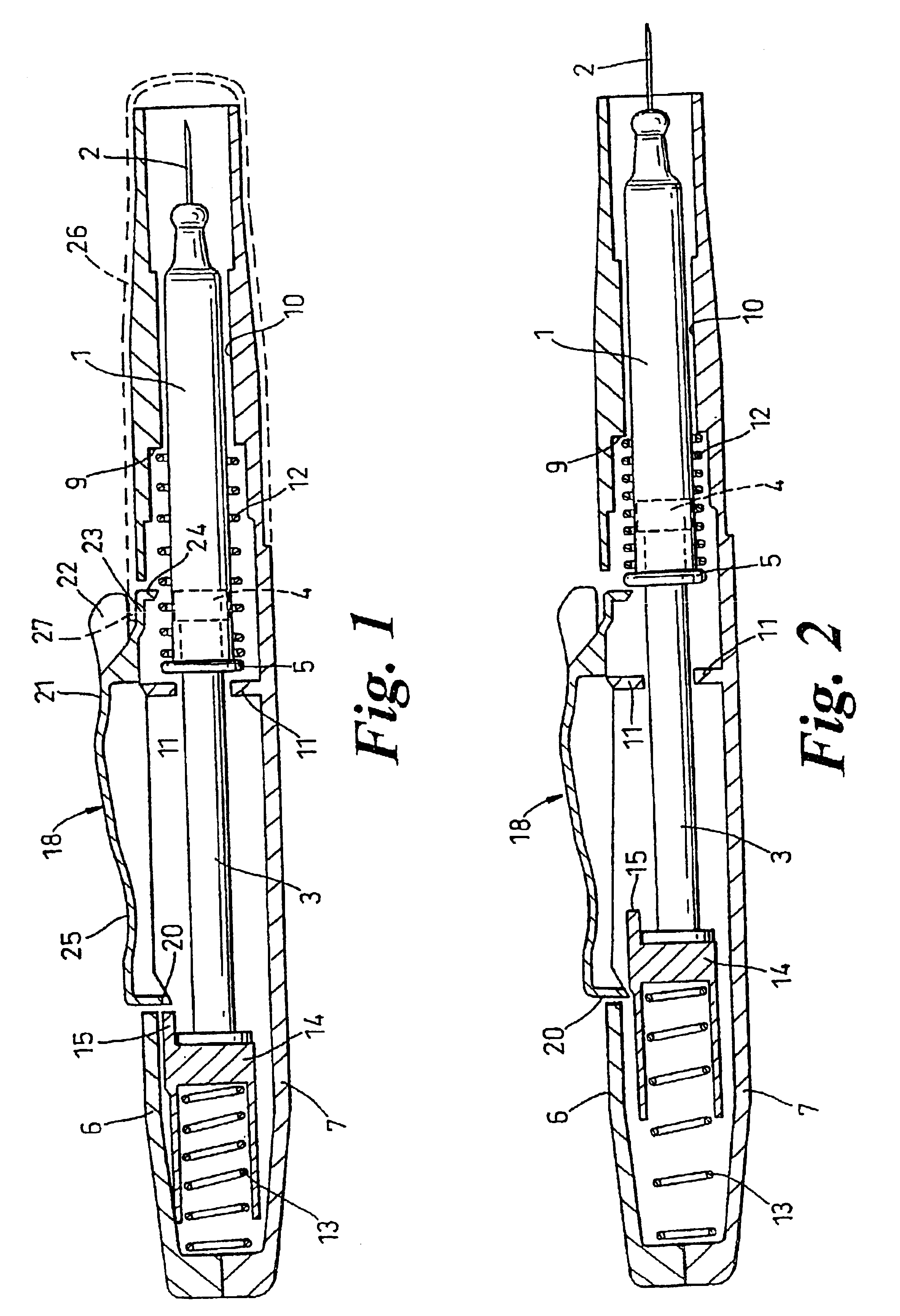
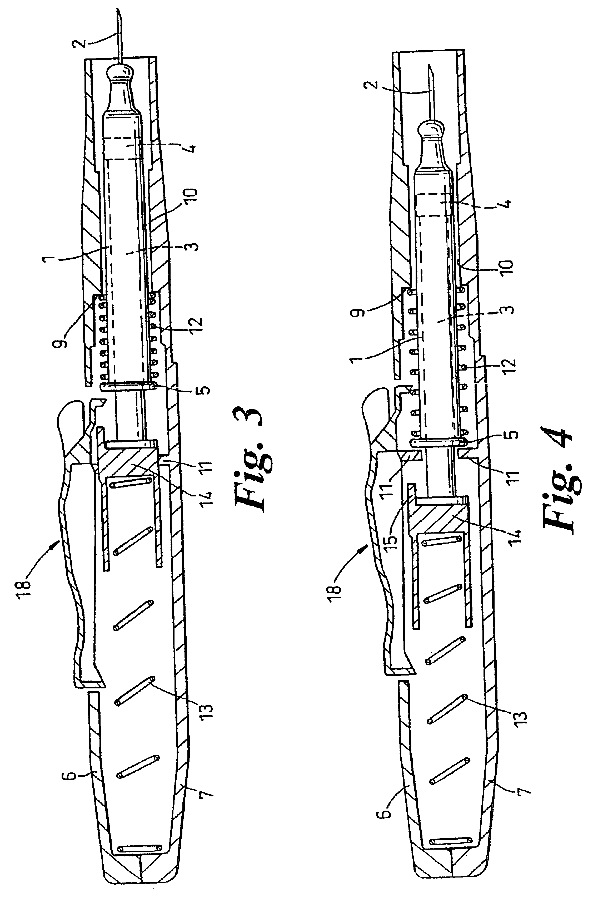
[0018]The injection device is designed to contain and operate a syringe having a capsule 1, a needle 2 at its forward end, and a plunger 3 at its rearward end which can actuate a piston 4 within the capsule to eject a dose through the needle 2. The rear end of the capsule has an outwardly projecting rim 5. This syringe is of known form.

[0019]The body of the injection device is formed by two generally semi-cylindrical halves 6 and 7 brought together and secured by adhesive or welding for example, or by snap-fitting lugs and sockets, to make a barrel with tapers at each end. The halves 6 and 7 are moulded in one piece in an opened-out condition, being joined by a single long web, or several shorter webs 8. These extend along one pair of adjacent longitudinal edges of the halves 6 and 7 between the tapering ends, and serve as hinges when the halves are closed together.

[0020]Towards its forward end the body reduces internally at a shoulder 9 to a passage 10 which serves as a longitudina...


PUM


Abstract

A one-shot throwaway injection device has a barrel that houses a syringe initially in a retracted state held back by a trigger against a drive spring. Actuation of the trigger causes the syringe to be thrust forwards by the spring acting on its plunger until the needle is fully projecting, and then the dose is ejected by the final expansion of the spring. Release of the trigger allows a return spring to urge the syringe back and retract the needle. The barrel is a unitary plastics moulding of two longitudinally split halves hinged together with the trigger integrally formed with one of these halves. The other components and the syringe are positioned in one half which is then closed up and fastened to the other half to complete the barrel.

Description

[0001]This application is a continuation of application Ser. No. 09 / 462,366, filed on Jan. 7, 2000 now abandoned. Application Ser. No. 09 / 462,366 is the national phase of PCT International Application No. PCT / GB98 / 02103 filed on Jul. 16, 1998 under 35 U.S.C. § 371. The entire contents of each of the above-identified applications are hereby incorporated by reference.BACKGROUND OF THE INVENTION[0002]This invention relates to injection devices.[0003]It concerns devices which are fitted with a syringe having a capsule with a needle projecting from the forward end and a plunger from the rear end. A trigger and spring mechanism, when operated, shoots the syringe forwardly to project the needle, and then continues to act on the plunger to eject the dose. There is also a return spring arrangement to retract the needle after use, thereby making it safe.[0004]Hitherto, these firing devices have been quite complicated and expensive, and it is necessary to load and unload the syringe before and...

Claims


Application Information

Patent Timeline
Patent Type & Authority Patents(United States)
IPC IPC(8): A61M5/00A61M5/20A61M5/28A61M5/32
CPCA61M5/2033A61M5/28A61M2005/2073A61M5/3257A61M2005/206A61M5/3202
Inventor CROSSMAN, DAVID DANVERSMARSHALL, JEREMY
Owner OWEN MUMFORD
Why Eureka
Try Eureka