Phase error cancellation

a phase error and phase correction technology, applied in the direction of electrical equipment, pulse automatic control, etc., can solve the problems of phase error correction signal to have a significant energy spectrum, noise shaping techniques may not meet stringent noise specifications, phase errors are introduced into the vco output signal, etc., to limit the low pass filter effect

Active Publication Date: 2006-06-27
SKYWORKS SOLUTIONS INC
View PDF18 Cites 31 Cited by
  • Summary
  • Abstract
  • Description
  • Claims
  • Application Information

AI Technical Summary

Benefits of technology

[0009]In one embodiment a method is provided for generating a noise cancellation signal in a fractional-N phase-locked loop. The method includes supplying a divide value to a first delta sigma modulator and generating a divide control signal in a first delta sigma modulator to control a divide value of a feedback divider in the phase-locked loop. The first delta sigma modulator integrates an error term indicative of a difference between a value of the generated divide control signal and the divide value supplied to the first delta sigma modulator. A phase error cancellation signal is generated by quantizing the integrated error term using a second delta sigma modulator. The method may further include utilizing the error term in the second delta sigma modulator in the process of quantizing the integrated error term, thereby limiting the low pass filter effects of the second delta sigma modulator in the cancellation signal.

Problems solved by technology

In that way, the PLL outputs a signal having an average frequency corresponding to M. However, while the average frequency output may be correct, phase errors are introduced into the VCO output signal because the divide ratio M′ is not equal to the desired divide ratio M.
However, the digital phase error correction signal generally has significantly more bits than can be converted accurately or quickly enough by a digital to analog converter (DAC), so the digital phase error correction signal is typically truncated prior to being supplied to the DAC.
However, simply truncating the phase error correction signal causes the phase error correction signal to have a noise spectrum that has significant energy in frequency bands of interest.
However, for certain applications some noise shaping techniques may not meet stringent noise specifications.

Method used


Image

  • Phase error cancellation
  • Phase error cancellation
  • Phase error cancellation

Examples


Embodiment Construction

)

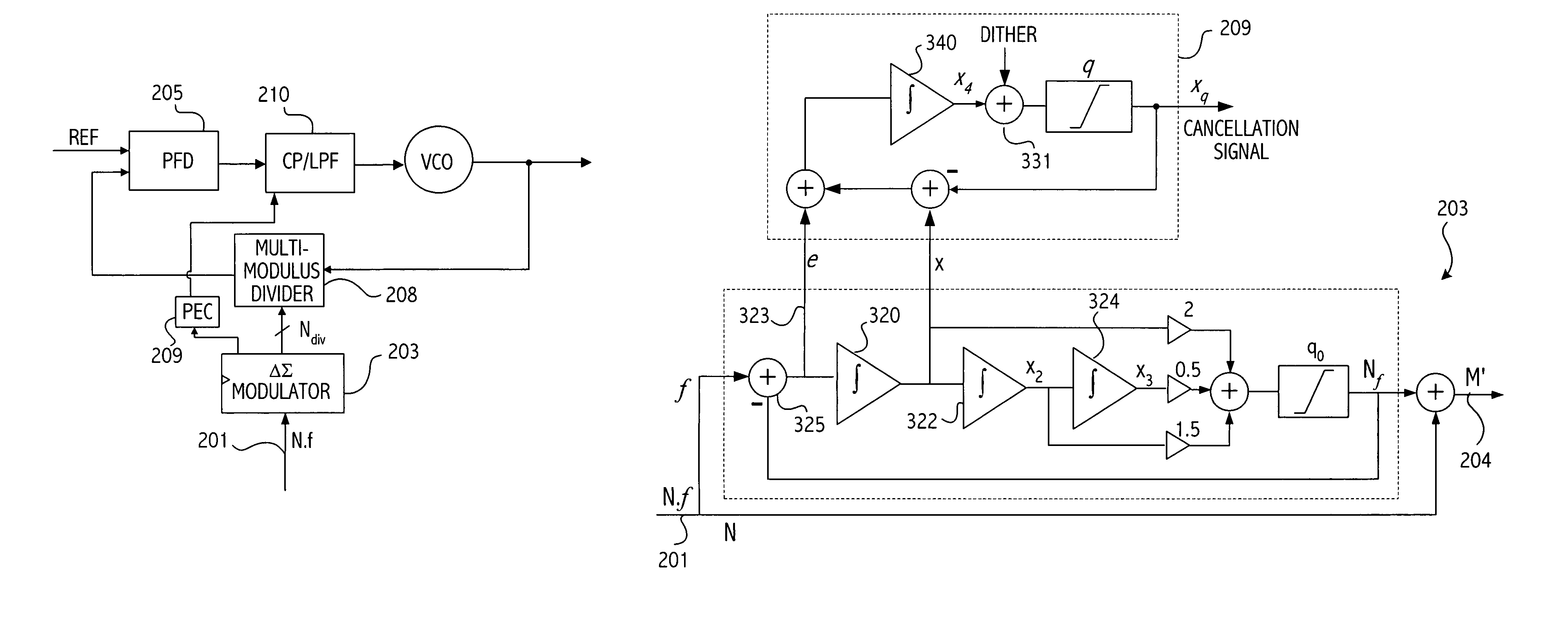
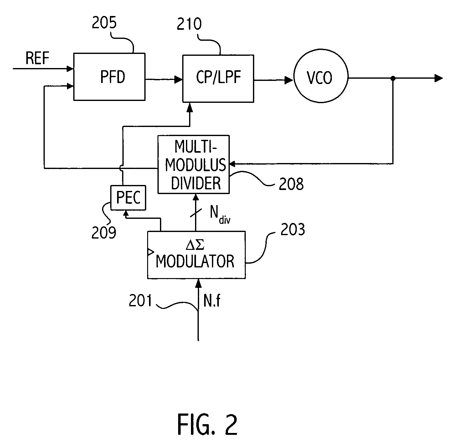
[0019]FIG. 2 illustrates an exemplary system that can utilize the phase error correction approach described herein. Referring again to FIG. 2, the divide control signal N.f supplied on node 201 is a rational number having an integer portion N and a fractional portion f. The divide control signal may be a slowly varying fractional-N divide signal that drives the delta-sigma modulator 203. The delta sigma modulator 203 produces a sequence of integers Ndiv close in value to the divide signal N.f, in such a way that the average value of Ndiv equals the divide signal N.f. Because integers are always somewhat different than the divide signal value, a phase error, Δφ, is produced at each update time. By carefully following the action of the system the net result of these phase errors at the input of the PLL—that is, at the input to phase and frequency detector (PFD) 205 can be determined. The phase error correction (PEC) circuit 209 is utilized to generate the phase error correction signa...


PUM


Abstract

A noise cancellation signal is generated for a fractional-N phase-locked loop by supplying a divide value to a first delta sigma modulator and generating a divide control signal in a first delta sigma modulator to control a divide value of a feedback divider in the phase-locked loop. The first delta sigma modulator integrates an error term indicative of a difference between a value of the generated divide control signal and the divide value supplied to the first delta sigma modulator. A phase error cancellation signal is generated by quantizing the integrated error term using a second delta sigma modulator. The error term can be used by the second delta sigma modulator while quantizing the integrated error term, thereby limiting the low pass filter effects of the second delta sigma modulator in the cancellation signal.

Description

CROSS-REFERENCE TO RELATED APPLICATION(S)BACKGROUND[0001]1. Field of the Invention[0002]This invention relates to phase-locked loops and more particularly to phase error correction in phase-locked loops.[0003]2. Description of the Related Art[0004]Phased-locked loops (PLLs) control an oscillator output signal so that it maintains a desired relationship with an input reference signal. The desired relationship may be to maintain a particular phase / frequency relationship with the input reference signal. PLL circuits are commonly used to multiply and divide the input reference signal. Some PLL implementations restrict the PLL output signal to be an integer multiple of an input reference signal supplied to the PLL. Other PLL implementations provide more versatility and allow the PLL output signal to be a non-integer multiple of the input reference signal. FIG. 1 illustrates one such PLL known as a fractional-N phase-locked loop.[0005]The PLL 100 compares the reference signal supplied on ...

Claims


Application Information

Patent Timeline
Patent Type & Authority Patents(United States)
IPC IPC(8): H03L7/00H03L7/089H03L7/197
CPCH03L7/1976H03L7/0891
Inventor FREY, DOUGTHOMSEN, AXELZHANG, LIGANG
Owner SKYWORKS SOLUTIONS INC
Why Eureka
Try Eureka