Adjusting track density by changing PES algorithm when servo writing a disk drive from spiral tracks

a technology of spiral tracks and density, applied in the field of disk drives, can solve the problems of not disclosing how to optimize the track, requiring a clean room environment, and high cost of external servo writers,

US7068459B1Inactive Publication Date: 2006-06-27WESTERN DIGITAL TECH INC
17 Cites 174 Cited by

Patent Information

Authority / Receiving Office
US · United States
Patent Type
Patents(United States)
Current Assignee / Owner
Publication Date
2006-06-27
Estimated Expiration
Not applicable · inactive patent

Smart Images

  • Figure 1
    Figure 1
  • Figure 2
    Figure 2
  • Figure 3
    Figure 3
Patent Text Reader

Abstract

A method and apparatus is disclosed for writing product servo sectors to a disk of a disk drive to define a plurality of data tracks. The disk drive comprises the disk and a head actuated over the disk. The disk comprises a plurality of spiral tracks which are read using the head to synchronize a write clock and to generate a position error signal (PES) according to a PES algorithm used to maintain the head along a first servo track while writing product servo sectors along the first servo track. The PES algorithm is adjusted to seek the head to a second servo track, and the head is used to write product servo sectors along the second servo track.
Need to check novelty before this filing date? Find Prior Art

Description

BACKGROUND OF THE INVENTION

[0001] 1. Field of the Invention

[0002] The present invention relates to disk drives for computer systems. More particularly, the present invention relates to adjusting the track density by changing the position error signal (PES) algorithm when servo writing a disk drive from spiral tracks.

[0003] 2. Description of the Prior Art

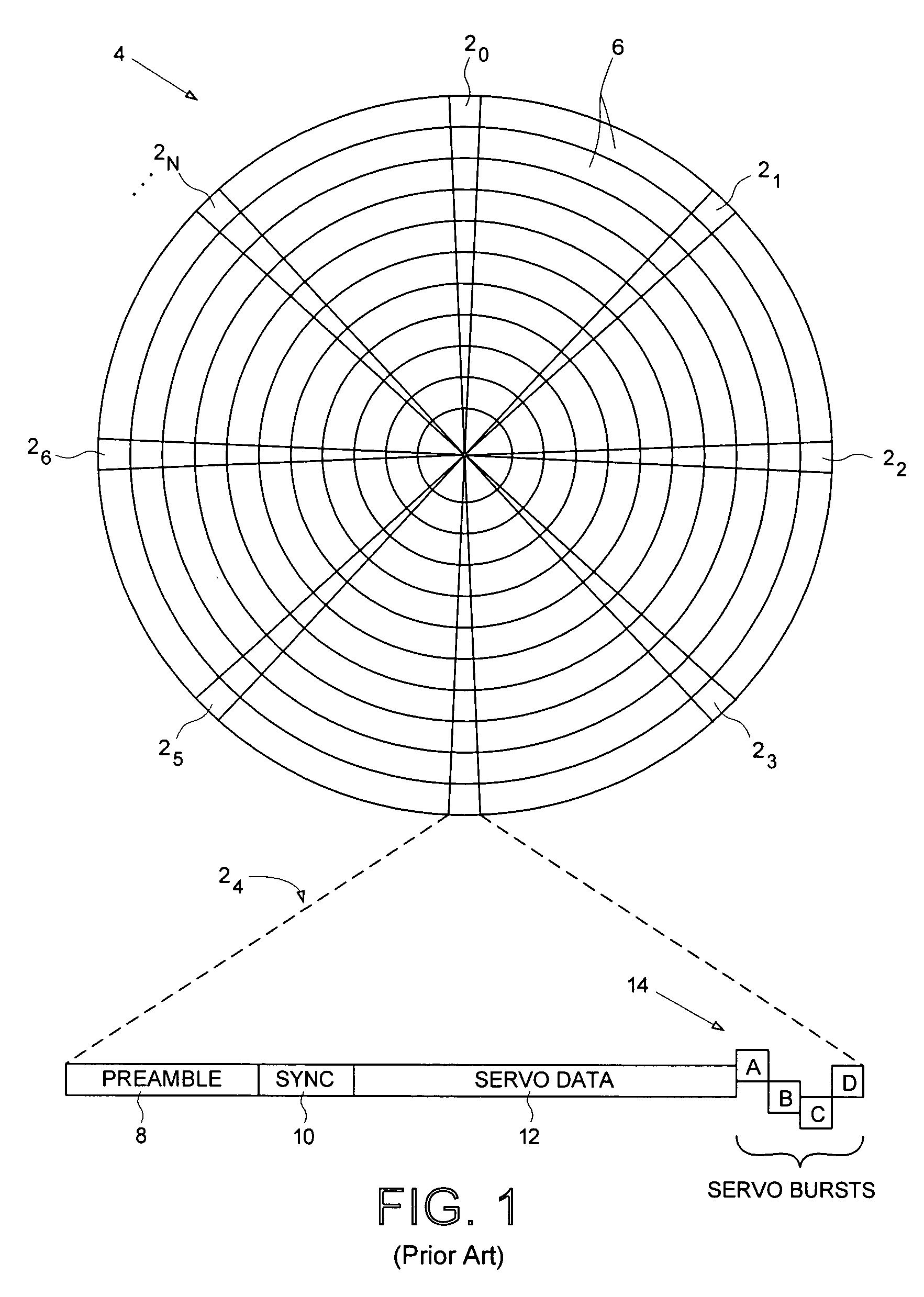
[0004] When manufacturing a disk drive, servo sectors 20–2N are written to a disk 4 which define a plurality of radially-spaced, concentric data tracks 6 as shown in the prior art disk format of FIG. 1. Each data track 6 is partitioned into a plurality of data sectors wherein the servo sectors 20–2N are considered “embedded” in the data sectors. Each, servo sector (e.g., servo sector 24) comprises a preamble 8 for synchronizing gain control and timing recovery, a sync mark 10 for synchronizing to a data field 12 comprising coarse head positioning information such as a track number, and servo bursts 14 which provide fine head positioning ...

Examples

Embodiment Construction

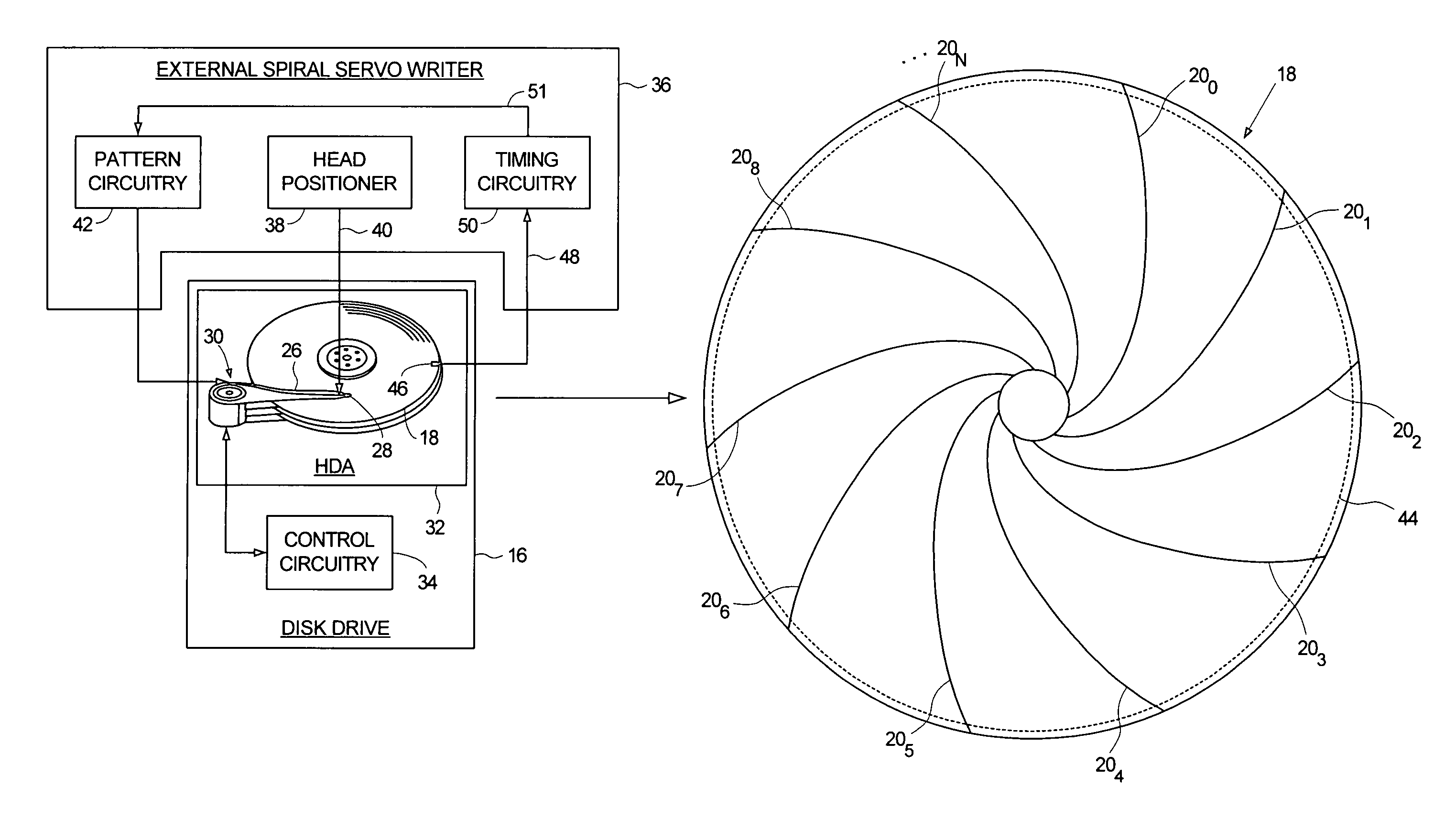
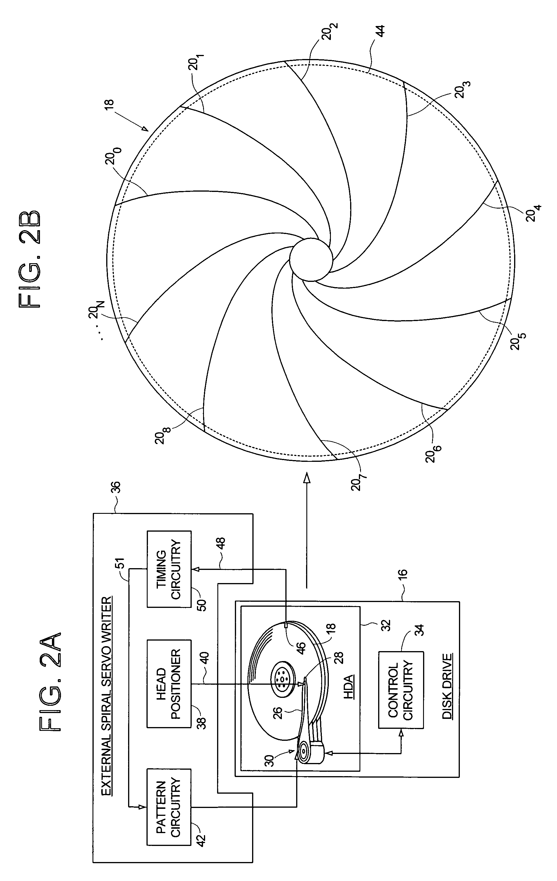
[0042]FIGS. 2A and 2B show an embodiment of the present invention wherein a plurality of spiral tracks 200–20N are written to a disk 18 of a disk drive 16 using an external spiral servo writer 36 (in an alternative embodiment, the spiral tracks are stamped onto the disk using magnetic printing techniques). The disk drive 16 comprises control circuitry 34 and a head disk assembly (HDA) 32 comprising the disk 18, an actuator arm 26, a head 28 coupled to a distal end of the actuator arm 26, and a voice coil motor 30 for rotating the actuator arm 26 about a pivot to position the head 28 radially over the disk 18. A write clock is synchronized to the rotation of the disk 18, and the plurality of spiral tracks 200–20N are written on the disk 18 at a predetermined circular location determined from the write clock. In one embodiment, each spiral track 20i comprises a high frequency signal 22 (FIG. 4B) interrupted at a predetermined interval by a sync mark 24.

[0043]The external spiral servo ...