Adjustable flow guide to accommodate electrode erosion in a gas discharge laser

a gas discharge laser and flow guide technology, which is applied in the direction of laser details, electrical equipment, active medium materials, etc., can solve the problems of poor laser performance, undesirable arcing between the electrodes, and gas unsuitable for the next puls

Active Publication Date: 2006-06-27
CYMER INC
View PDF7 Cites 29 Cited by
  • Summary
  • Abstract
  • Description
  • Claims
  • Application Information

AI Technical Summary

Problems solved by technology

Each discharge alters the physical condition of the gas in the discharge region rendering the gas unsuitable for use in the next pulse.
In particular, turbulence can develop near the discharge electrodes and cause undesirable arcing between the electrodes.
This arcing, in turn, may result in poor laser performance, including, but not limited to, lowered pulse energy and lowered pulse-to-pulse energy stability.
For the above-described arrangement

Method used


Image

  • Adjustable flow guide to accommodate electrode erosion in a gas discharge laser
  • Adjustable flow guide to accommodate electrode erosion in a gas discharge laser
  • Adjustable flow guide to accommodate electrode erosion in a gas discharge laser

Examples


Embodiment Construction

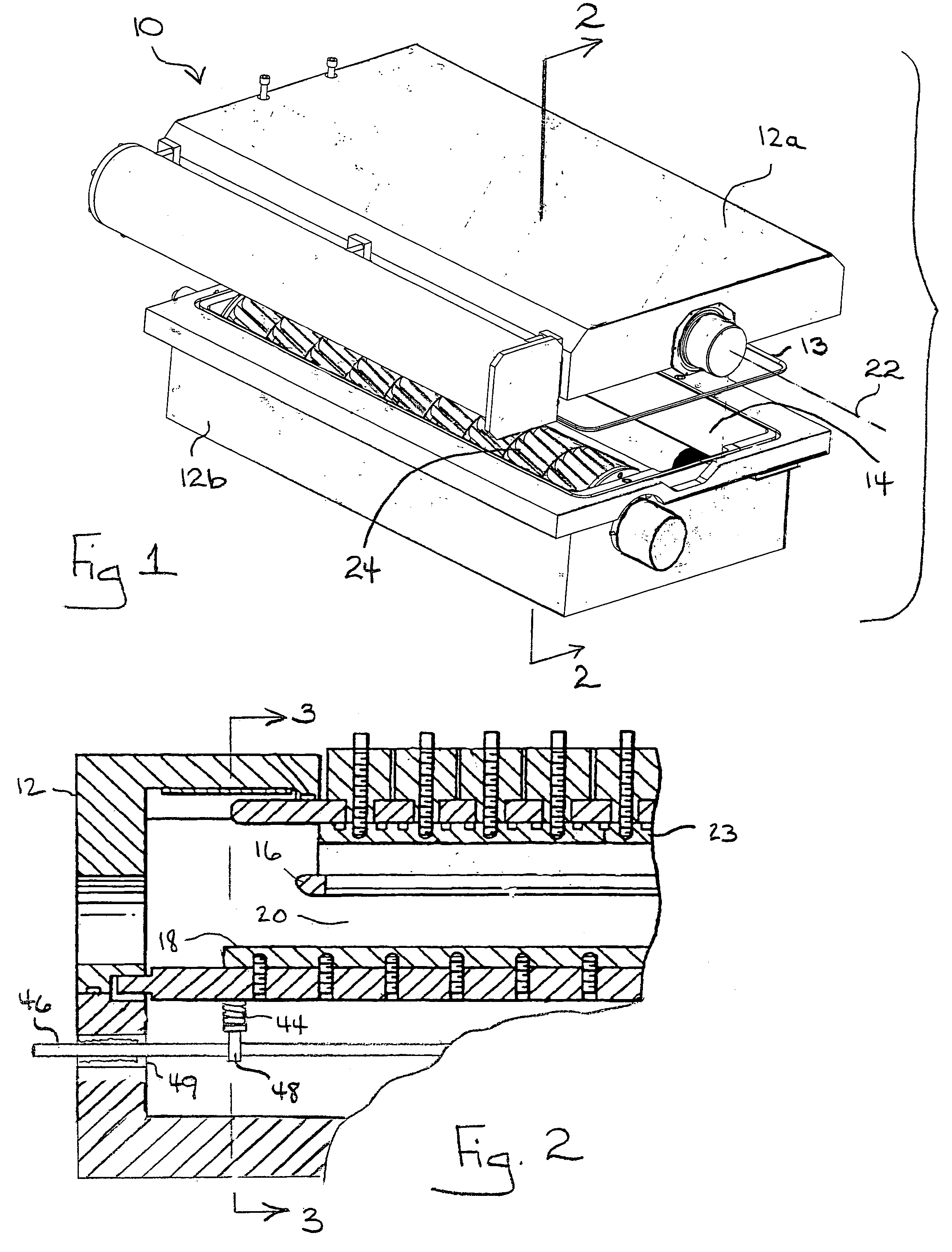
[0014]Referring initially to FIG. 1, a chamber for a pulsed, gas discharge laser, such as an excimer laser (e.g. KrF, ArF, XeF, XeCl, etc.) or molecular fluorine laser, is shown and generally designated 10. As shown, the chamber 10 typically includes a two-part chamber housing 12a,b that may be made of a relatively strong, corrosion resistant material, e.g. nickel plated aluminum, and is generally rectangular in construction with closed ends. With this structure, the housing components 12a,b and seal 13 may surround and enclose a volume 14 which may hold a laserable gas.

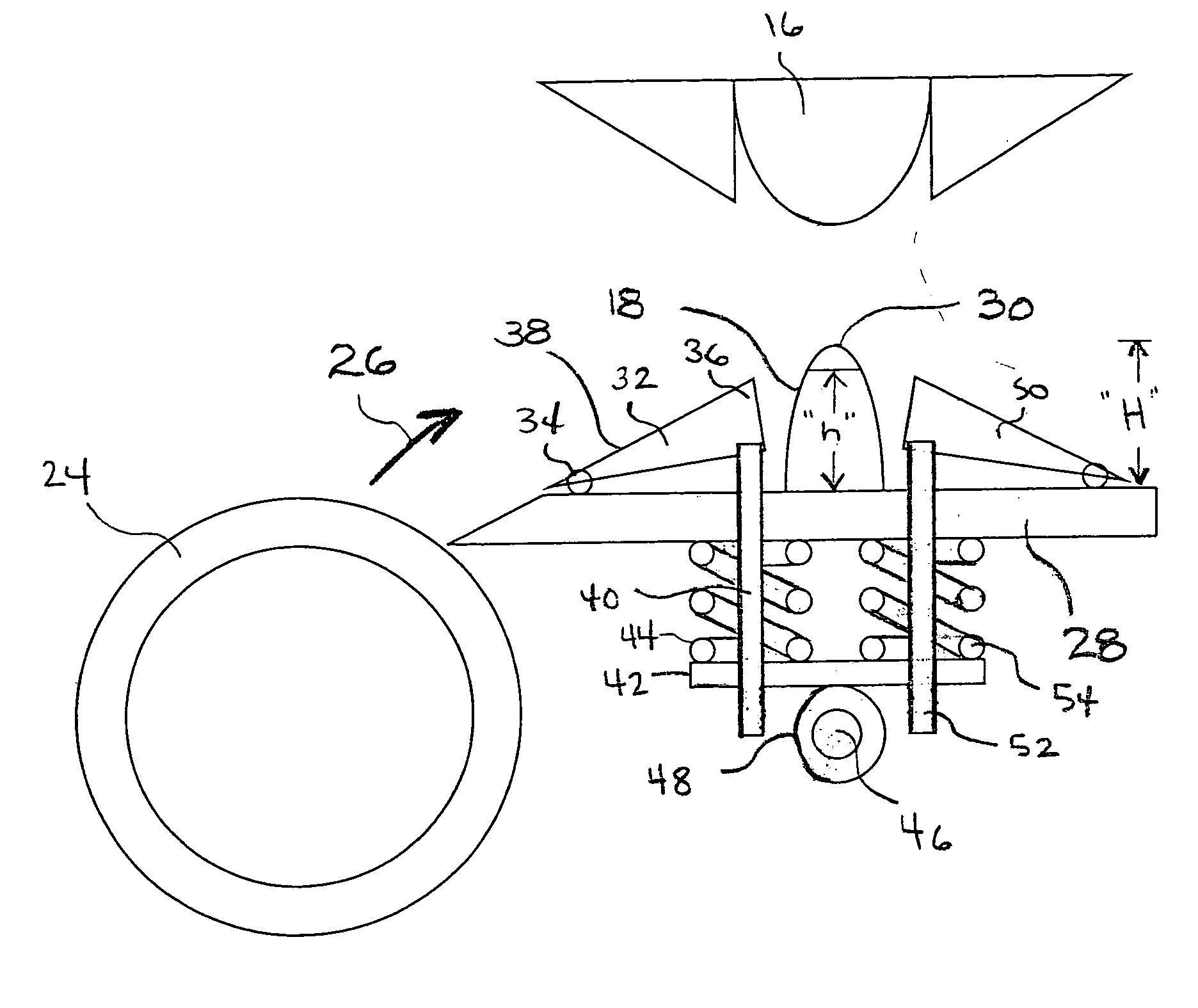
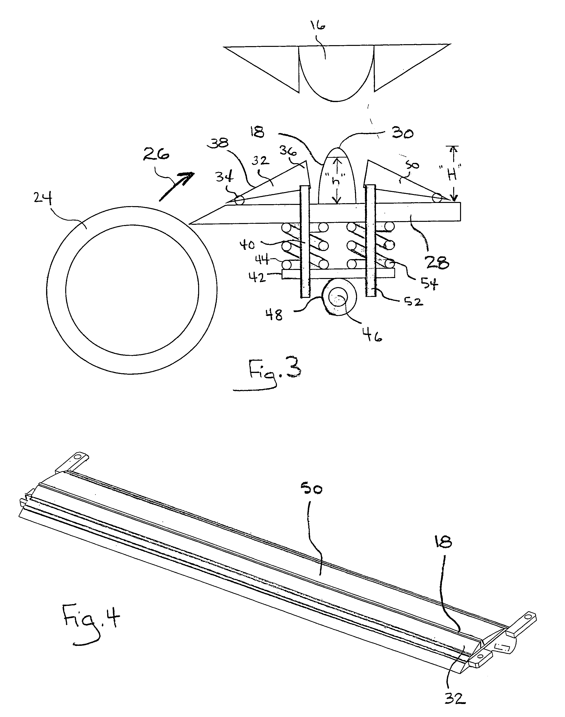
[0015]FIG. 2 shows that the chamber 10 may also include a gas discharge sub-system having two spaced apart electrodes 16, 18, one of which may be designated a cathode and the other an anode. With this arrangement, a gas discharge region 20 is established in the space between the electrodes 16, 18 which includes the laser's beam axis 22 (axis 22 shown in FIG. 1). Each electrode 16, 18 may be elongated, for example, to...


PUM


Abstract

A laser and method for operating a laser and disclosed. The laser may include a first discharge electrode and a second discharge electrode positioned at a distance from the first electrode. A laserable gas may be provided together with a circulation system to flow the gas into a space between the electrodes. A voltage source may be connected to the electrodes for creating a discharge in the space; and a flow guide having a guide surface in contact with the gas may be provided that is guide selectively moveable relative to the first electrode to guide a flow of gas into the space. In one implementation, the flow guide directs flow toward an extremity of the first electrode and is adjustable to direct flow toward the extremity as the first electrode wears.

Description

FIELD OF THE INVENTION[0001]The present invention relates to pulsed, gas discharge lasers. The present invention is particularly, but not exclusively useful as a gas discharge laser having one or more discharge electrodes that wear down (e.g. erode) over the lifetime of the laser.BACKGROUND OF THE INVENTION[0002]Modern pulsed, high repetition rate, gas discharge lasers such as ArF XeF and Krf excimer lasers and molecular fluorine lasers generally employ a pair of spaced apart, elongated (e.g. 30 cm long) main discharge electrodes to initiate lasing in a gaseous material. For example, each pulse may be produced by applying a very high, voltage potential across the electrodes with a power supply which causes a discharge between the electrodes having a duration of about 30 nanoseconds. A typical discharge may deposit about 2.5 J of energy into a gain region that is about 20 mm high, 3 mm wide and 500 mm long.[0003]Each discharge alters the physical condition of the gas in the discharge...

Claims


Application Information

Patent Timeline
IPC IPC(8): H01S3/22
CPCH01S3/036H01S3/097H01S3/038H01S3/2251H01S3/225
Inventor AMADA, YOSHIHOMORTON, RICHARD G.MOOSMAN, BRYAN G.
Owner CYMER INC
Why Eureka
Try Eureka