Data transmission method and radio system

a data transmission and radio system technology, applied in the field of data transmission methods, can solve the problems of large differences in load, inoptimized selection method, and uneven load in the power amplifier of the transceiver, and achieve the effects of improving the reliability of antenna selection, reducing load unevenness, and implementing a flexible operating radio system

Inactive Publication Date: 2006-06-27
NOKIA NETWORKS OY
View PDF13 Cites 30 Cited by
  • Summary
  • Abstract
  • Description
  • Claims
  • Application Information

AI Technical Summary

Benefits of technology

[0016]The data transmission method and radio system of the invention provide several advantages. With the method of the invention, the load of the amplifiers in the base station of the radio system can continuously be distributed as evenly as possible between each amplifier. Since the load remains even, the dynamics of the amplifiers need not be as extensive as in amplifiers used in prior art radio systems, thus facilitating the design of amplifiers.
[0017]The method minimizes the unevenness of load between power amplifiers by letting the base station select the transmission antenna of a downlink transmission, when necessary. If the base station uses adaptive antennas, the method of the invention makes it possible to select a transmission direction which causes as little interference as possible to the other signals in the radio network.
[0018]In addition, the method makes it possible to implement a flexibly operating radio system. In a receiver, which is a subscriber terminal, of the radio system of the invention, the received signals are categorized by means of threshold levels into different signal groups. Using several thresholds makes it possible to allocate channels more flexibly to receivers. In addition, using thresholds improves the reliability of the antenna selection. The solution of the invention is relatively easy to implement by altering signalling, for instance.

Problems solved by technology

However, the use of STD methods causes load problems in the power amplifiers of the transceiver.
The problems are caused because the load of the power amplifiers is not always distributed evenly between the various power amplifiers, and the differences in loads may be relatively big.
The selection method is, however, not optimal from the point of view of the power amplifier load, since the used method may lead to overload in the power amplifier feeding the selected transmission antenna.
The load of the power amplifiers is thus too uneven in some situations.
Said problems are at least partly caused by the fact that measuring the signal quality is based on absolute values which does not lead to the best possible solution for the operation of the system.

Method used


Image

  • Data transmission method and radio system
  • Data transmission method and radio system
  • Data transmission method and radio system

Examples


Embodiment Construction

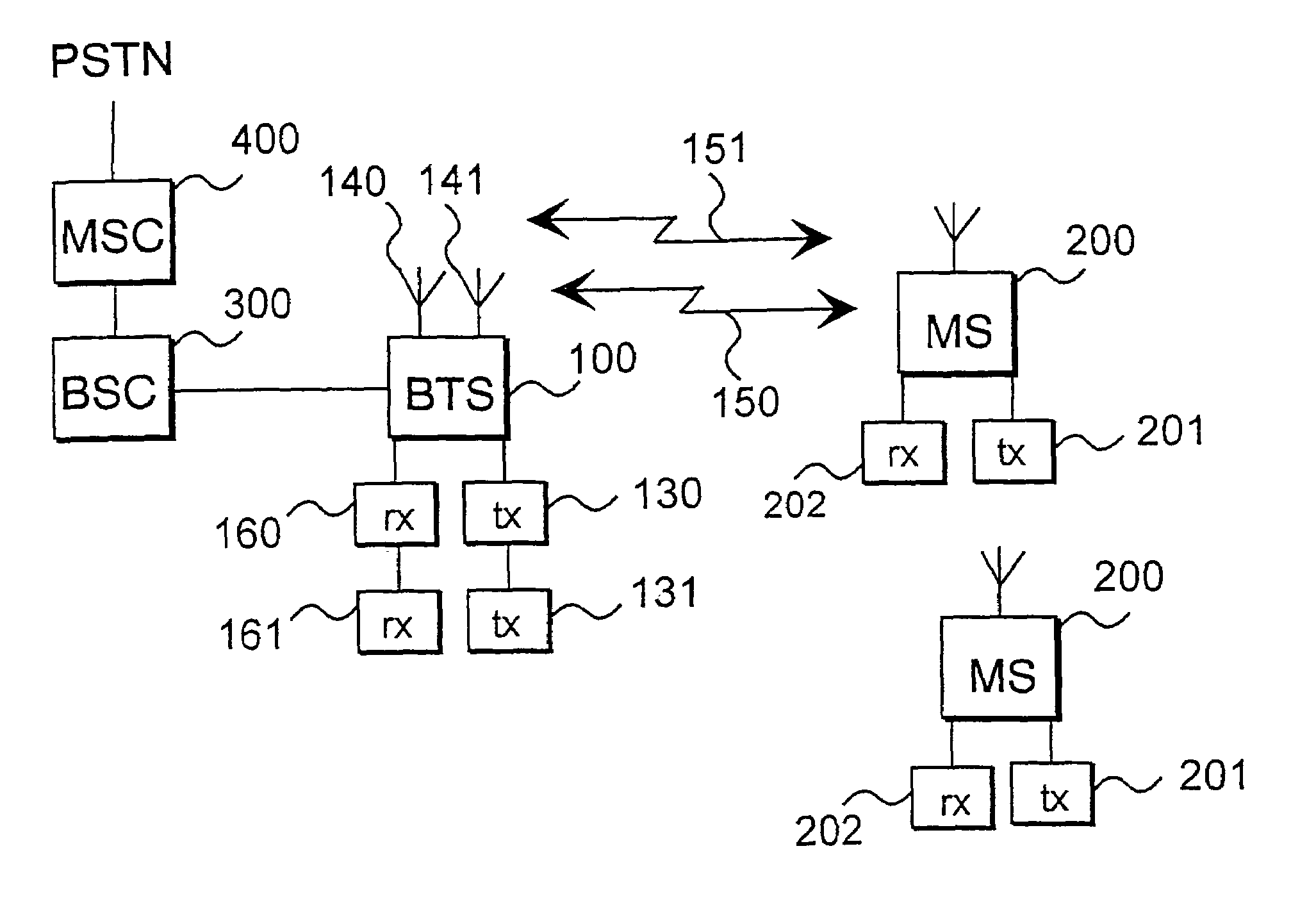
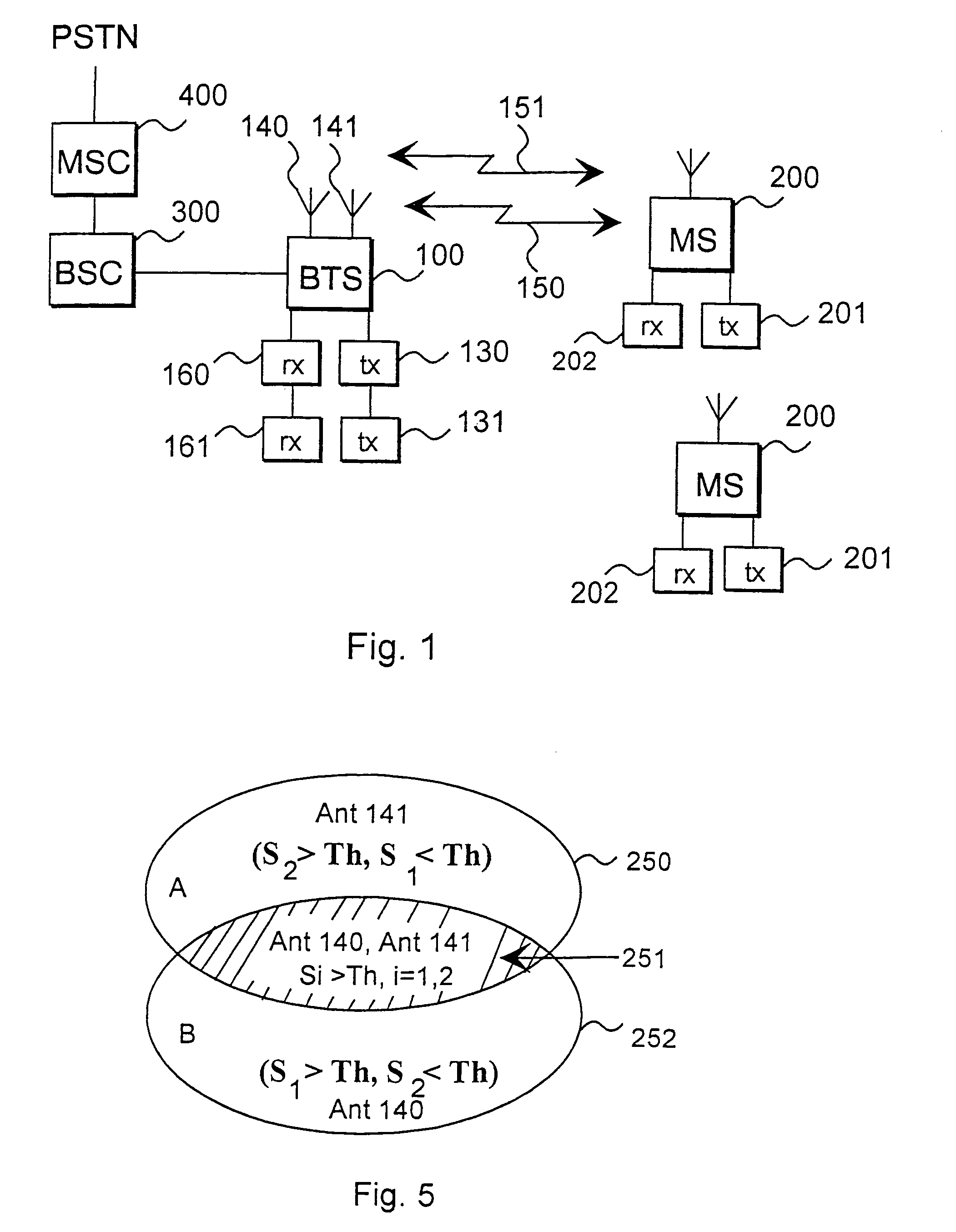
[0026]FIG. 1 shows a radio system comprising a base station 100, subscriber terminals 200, a base station controller 300 and a mobile switching centre 400. The subscriber terminals 200 can be mobile phones, for instance. The base station comprises transmitters 130, 131 and receivers 160, 161. In addition, the base station comprises antennas 140, 141 with which the base station transmits and receives signals. The base station transmits to a subscriber terminal and receives from a subscriber terminal a signal 150 by means of its antenna 140. In addition, the base station transmits to a subscriber terminal and receives from a subscriber terminal a signal 151 by means of its antenna 141. The figure shows that the subscriber terminal comprises a transmitter 201 and a receiver 202. The subscriber terminal can receive signals transmitted from the various antennas of the base station. The signals containing the same information received by the subscriber terminal can also be transmitted by ...


PUM


Abstract

The invention relates to a data transmission method and a radio system comprising at least one subscriber terminal and at least one base station including an antenna, by means of which the base station transmits signals to the subscriber terminal. The subscriber terminal includes a measuring mechanism which determines the quality of the signals received by the subscriber terminal by comparing the received signals with at least one signal quality threshold level. When only one signal exceeds the threshold, the subscriber terminal sends to the base station, which transmitted the signal that exceeded the threshold, a command to use, when transmitting a signal to the subscriber terminal, the antenna with which the signal that exceeded the threshold was transmitted, or the transmission direction to which the signal that exceeded the threshold was transmitted.

Description

[0001]This application is the National Phase of International Application PCT / FI99 / 01062 filed Dec. 21, 1999 which designated the U.S. and that International Application was Published under PCT Article 21(2) in English.FIELD OF THE INVENTION[0002]The invention relates to a data transmission method used in a radio system comprising a subscriber terminal and at least one base station transmitting signals to the subscriber terminal by means of its antenna.BACKGROUND OF THE INVENTION[0003]In transmitting signals, prior art radio systems use various diversity methods to improve the quality of data transmission. Diversity methods include, for instance, orthogonal transmit diversity (OTD), time switching transmit diversity (TSTD) and selective transmit diversity (STD). The above-mentioned diversity methods can be used in future WCDMA systems, for instance. Said methods improve BER performance, for instance, in data transmission. Of the above-mentioned methods, especially the STD method pro...

Claims


Application Information

Patent Timeline
Patent Type & Authority Patents(United States)
IPC IPC(8): H04Q7/20H04J13/00H04B7/06
CPCH04B7/061H04B7/0689H04B7/0632
Inventor KATZ, MARCOS
Owner NOKIA NETWORKS OY
Why Eureka
Try Eureka