Method and apparatus for reducing scheduling conflicts for a resource

a scheduling conflict and resource technology, applied in the field of automatic manufacturing environments, can solve the problems of process tool idleness, lack of advance scheduling, and inability to support highly automated factory operations

Inactive Publication Date: 2006-06-27
GLOBALFOUNDRIES US INC
View PDF22 Cites 34 Cited by
  • Summary
  • Abstract
  • Description
  • Claims
  • Application Information

AI Technical Summary

Benefits of technology

[0020]One aspect of the present invention is seen in a method that includes providing a schedule of engagements for a resource. Each engagement has a working window and an associated engagement density function. The engagement density functions of the scheduled engagements are combined to generate a committed capacity function for the resource. A region of violation in the committed capacity function is identified where the committed capacity of the resource exceeds a capacity threshold. An area of a region of overlap between the working window of a selected one of the engagements and the region of violation is determined. An area reduction amount for the selected engagement is determined based on a portion of the area of the region of overlap. The working window of the selected engagement is changed based on the area reduction amount.
[0021]Another aspect of the present invention is seen in a syste

Problems solved by technology

Although MES systems are sufficient for tracking lots and machines, such systems suffer several deficiencies, the most obvious of which are their passive nature, lack of advance scheduling, and inability to support highly automated factory operations.
If the WFT does not retrieve the lot soon enough, or neglects to initiate processing at the earliest available time, the process tool becomes idle and production is adversely impacted.
However, the presence of WFTs also inevitably introduces some inefficiencies.
Typically, there may be a significant difference between the performance of the best WFT and the performance of the worst WFT.
A WFT typically simultaneously monitors the processing of many tools, making it difficult to focus on an individual lot or tool.
Furthermore, the size and complexity of the modern fabrication process flows makes it exceedingly difficult for a WFT to foresee and prevent downstream bottlenecks or shortages arising from upstream bottlenecks.
Shift changes, rest breaks, and days off for the WFT also create inefficiencies or downtime that adversely impact the manufacturing process flow.
Thus, factory control systems utilized in today's wafer fabs are

Method used


Image

  • Method and apparatus for reducing scheduling conflicts for a resource
  • Method and apparatus for reducing scheduling conflicts for a resource
  • Method and apparatus for reducing scheduling conflicts for a resource

Examples


case 4

ww overlaps entirely within ROV):

RightArea4(t)=k

LeftArea4(t)=0

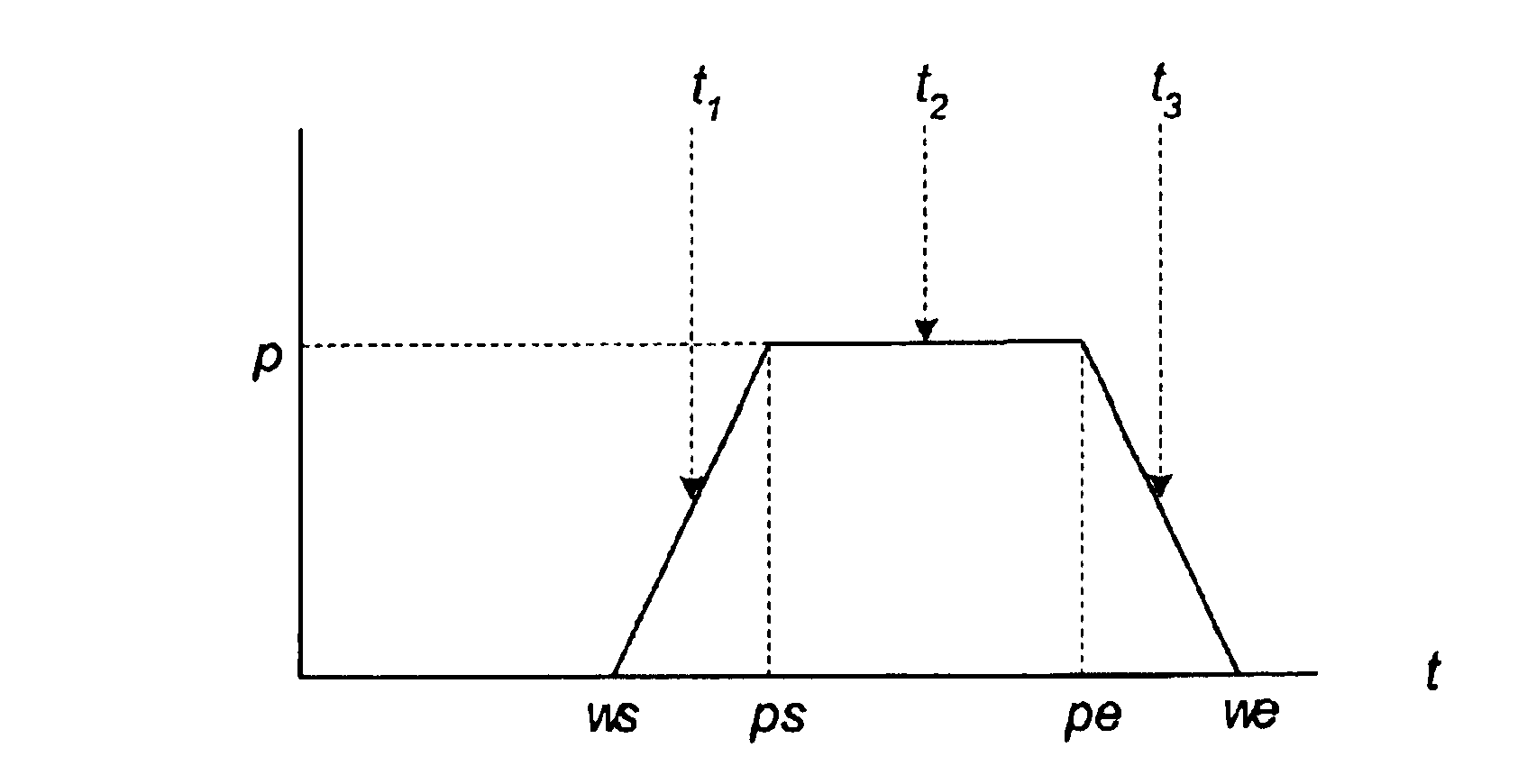
[0378]The situation shown in FIG. 13 falls in Case 2, and RightArea2(t=5.76, 1, 10, 2)=0.93.

[0379]There are two mechanisms for reducing the area that an engagement contributes to cc(t): shifting the whole engagement (presumably because the working window is smaller than the commitment window) and shrinking the working window. In the example scenario of FIG. 13, where the engagement is on the left end of the ROV, the engagement may be shifted left or shrunk by moving its right end to the left. The machine scheduling agent 410 calculates how much to shift or shrink the working window to realize a required amount of ROV reduction.

[0380]The excess area in the ROV is shown in FIG. 13 (the area under cc(t) but above cc(t)=1) is 6.24. By shifting the engagement represented by the trapezoid 1320 entirely out of the ROV area, 0.93 could be recovered as indicated above. However, in general, it may be desirable to take only a portio...

case 4 ′

Case 4′: we

[0399]Similar to the case 4, an engagement that entirely overlaps an ROV has three components that may contribute to the ROV: LeftRampArea, PlateauArea and RightRampArea. Depending on the AreaNeeded, part or all of these components may be required. The total shift Δt in this case has two parts: Δt,=t−we (which does not reduce any ROV), and Δt2=we′−t (which is the special case of Case 3′ when t=we), where we′ is the new window end after the shift. Thus, there are four subcases.

[0400]Subcase 4′.1: If AreaNeeded2 can be derived directly from the subcase 3′.1 with t=we, and that yields: Δ⁢ ⁢t2=-(s*p+pe-t)+(s*p+pe-t)2+8*s*AreaNeeded2.

Thus, the total shift is given by: Δ⁢ ⁢t=Δ⁢ ⁢t1+Δ⁢ ⁢t2=t-we+-(s*p+pe-t)+(s*p+pe-t)2+8*s*AreaNeeded2.

[0401]Subcase 4′2: If RightRampArea2 can be derived directly from the subcase 3′.2 with t=we, and that yields: Δ⁢ ⁢t2=(t-pe)*p*s2*s*p+AreaNeededp.

Thus, the total shift is given by: Δ⁢ ⁢...

case 1

s (shrink left)

[0416]This case is illustrated in FIG. 18. There are two subcases, depending on whether tps′. Because t

RightArea(t, ws, we, k)=k−(t−ws)2 / (2s).

The formula for RightArea(t, ws, we′, k) depends on whether tps′. For the subcase t

RightArea(t, ws, we′, k)=k−(t−ws)2 / (2s′)

However, to reach the subcase t>ps′, ps′ must have moved to the left, so p′=1, pe′=ws+k, and t is in the plateau, yielding:

RightArea(t, ws, we′, k)=pe′−t+s′ / 2=ws+k−t+s′ / 2.

This equation can be evaluated to determine the maximum area available in a given region. For example, the equation used above:

AreaNeeded=RightArea(t, ws, we, k)−RightArea(t, ws, we−Δt, k),

can be evaluated when ps′=t. If the AreaNeeded is less than that value, the case t0). If AreaNeeded is less than this value, the case t>ps′ is present. Otherwise, even if the window is shrunk to its kernel size, the required area cannot be recovered, and other sources ...


PUM


Abstract

A method includes providing a schedule of engagements for a resource. Each engagement has a working window and an associated engagement density function. The engagement density functions of the scheduled engagements are combined to generate a committed capacity function for the resource. A region of violation in the committed capacity function is identified where the committed capacity of the resource exceeds a capacity threshold. An area of a region of overlap between the working window of a selected one of the engagements and the region of violation is determined. An area reduction amount for the selected engagement is determined based on a portion of the area of the region of overlap. The working window of the selected engagement is changed based on the area reduction amount.

Description

[0001]The United States Government has a paid-up license in this invention and the right in limited circumstances to require the patent owner to license others on reasonable terms as provided for by the terms of Cooperative Agreement No. 70NANB7H3041 awarded by the United States Department of Commerce, National Institute of Standards and Technology (“NIST”), Advanced Technology Program (“ATP”).BACKGROUND OF THE INVENTION[0002]1. Field of the Invention[0003]This invention pertains to automated manufacturing environments, such as semiconductor manufacturing, and, more particularly, to a method and apparatus for reducing scheduling conflicts for a resource.[0004]2. Description of the Related Art[0005]Growing technological requirements and the worldwide acceptance of sophisticated electronic devices have created an unprecedented demand for large-scale, complex, integrated circuits. Competition in the semiconductor industry requires that products be designed, manufactured, and marketed i...

Claims


Application Information

Patent Timeline
IPC IPC(8): G06F19/00
CPCG06Q10/06
Inventor BARTO, LARRY D.LI, YIWEINETTLES, STEVEN C.PARUNAK, H. VAN DYKE
Owner GLOBALFOUNDRIES US INC
Why Eureka
Try Eureka