System and method for determining an angular position of a rotor and a radial position of the rotor

a technology of radial position and rotor, which is applied in the direction of converting sensor output electrically/magnetically, speed measurement using gyroscopic effects, instruments, etc., can solve the problem that second and third sensors cannot be disposed proximately

Active Publication Date: 2006-06-27
BAKER HUGHES INC
View PDF8 Cites 3 Cited by
  • Summary
  • Abstract
  • Description
  • Claims
  • Application Information

AI Technical Summary

Problems solved by technology

A significant drawback with this methodology, is that there may be only one accessible portion of the rotating machine (e.g., a single plane) where sensors can be disposed for monitoring the angular position and radial position of the rotor.
As a result, the second and third sensors cannot be disposed proximate a smooth outer surface of the rotor as desired for determining radial displacement of the rotor.

Method used


Image

  • System and method for determining an angular position of a rotor and a radial position of the rotor
  • System and method for determining an angular position of a rotor and a radial position of the rotor
  • System and method for determining an angular position of a rotor and a radial position of the rotor

Examples


Embodiment Construction

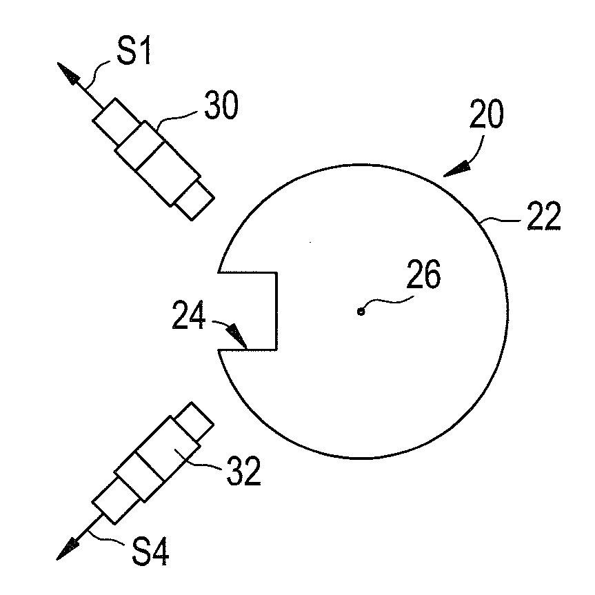
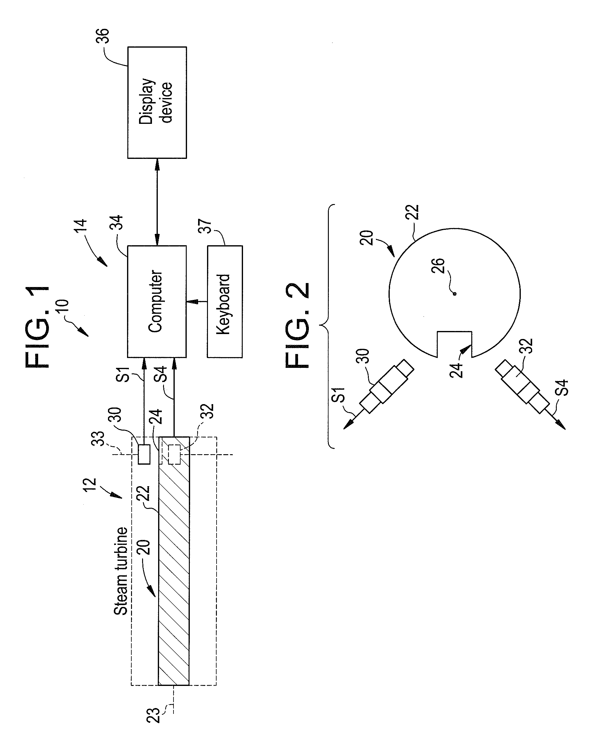
[0030]Referring to FIG. 1, a steam turbine system 10 having a steam turbine 12 and a monitoring system 14 is illustrated. The steam turbine 12 includes a rotor 20 configured to rotate about an axis 23. The rotor 20 comprises a cylindrical portion 22 having a slot 24 extending into the portion 22. In an alternate embodiment, the rotor 20 has a protrusion or key (not shown) extending radially outwardly from the portion 22 replacing the slot 24.

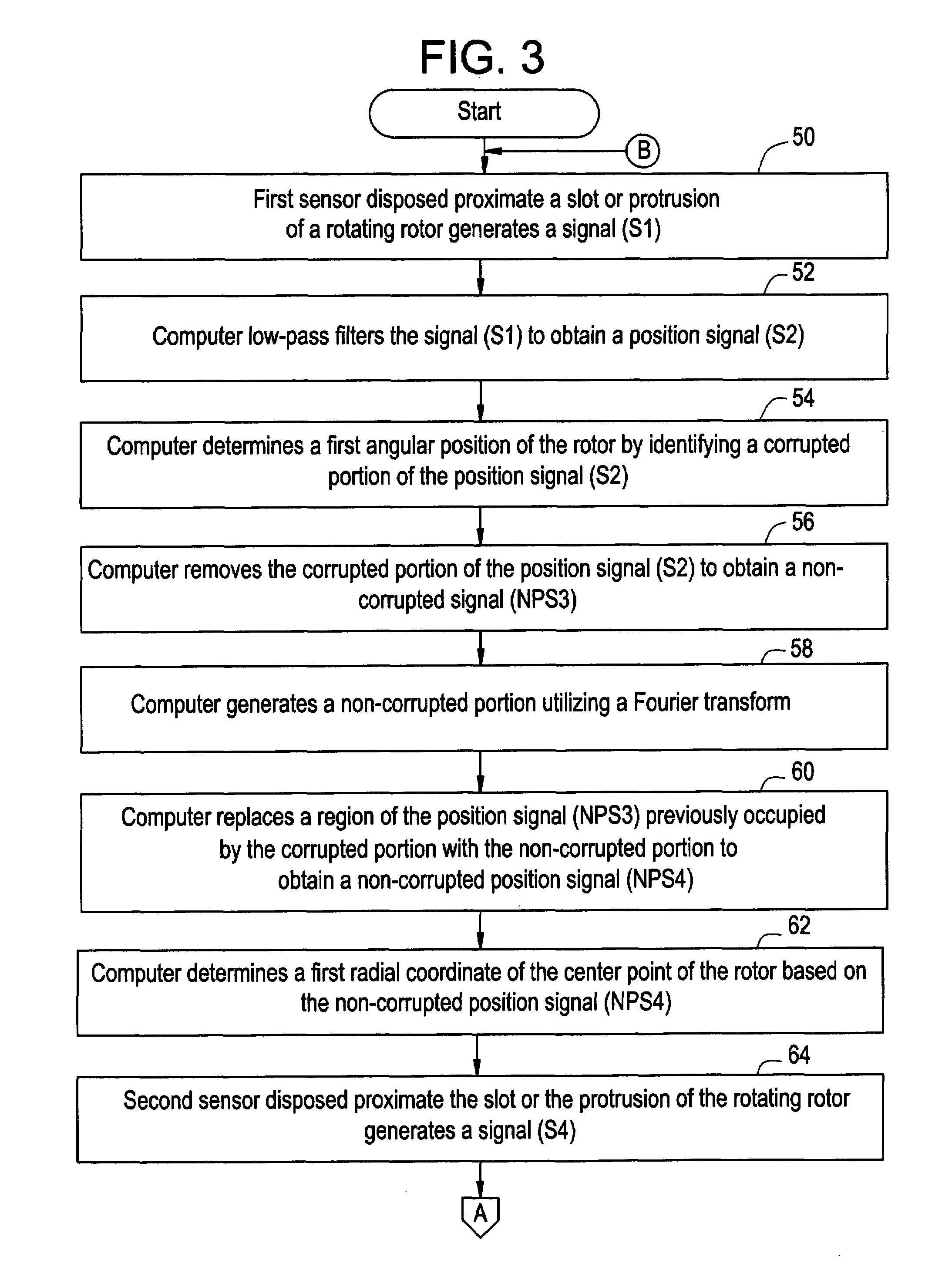
[0031]The monitoring system 14 is provided to determine both an angular position of the rotor 20 and a radial position of the rotor 20 during rotation of the rotor 20. During rotation of the rotor 20, the angular position of the rotor 20 constantly changes. Further, during rotation of the rotor 20, a center point 26 of the rotor 20 can cyclically move back and forth relative to the axis 23. Accordingly, a radial position of the rotor 20 also changes. The monitoring system 14 includes eddy current sensors 30, 32, a computer 34, a display device 3...


PUM


Abstract

A system and a method for determining an angular position of a rotor and a radial position of the rotor are provided. The rotor has either a slot or a protrusion on the rotor. The rotor is centered about a center point. The method includes generating a first signal utilizing a first sensor disposed proximate the slot or protrusion of the rotor. The method further includes determining a first angular position of the rotor by identifying a first corrupted portion of the first signal. The method further includes removing the first corrupted portion of the first signal to obtain a second non-corrupted position signal. The method further includes determining a first radial coordinate of the center point of the rotor based on the second non-corrupted position signal.

Description

BACKGROUND OF THE INVENTION[0001]Rotating machines, such as gas turbines, steam turbines, hydro-turbines, pumps and motors, rotate a rotor at predetermined speeds. To monitor the angular position of the rotor, a first sensor is disposed adjacent a keyway notch disposed in the rotor. The first sensor generates a signal indicating the position of the notch and thus the angular position of the rotor. The radial position of the rotor may also be monitored utilizing second and third sensors disposed on another plane of the rotor proximate a smooth outer surface of the rotor. The second and third sensors generate signals indicative of a radial position of the rotor.[0002]A significant drawback with this methodology, is that there may be only one accessible portion of the rotating machine (e.g., a single plane) where sensors can be disposed for monitoring the angular position and radial position of the rotor. Further, the accessible portion of the rotating machine may comprise a portion of...

Claims


Application Information

Patent Timeline
Patent Type & Authority Patents(United States)
IPC IPC(8): G01C19/00G01D5/20
CPCG01D5/202G01D5/20G01D5/244G01B7/30G01B21/22
Inventor GRANT, JOHN WESLEYSCHMID, JAMES J.FOSTER, CRAIG J.
Owner BAKER HUGHES INC
Why Eureka
Try Eureka