Transmission apparatus, reception apparatus, transmission method, and reception method

a technology of transmission apparatus and receiving apparatus, applied in the field of transmission apparatus, receiving apparatus, transmission method, and reception method, can solve problems such as the reduction of communication quality, and achieve the effect of improving communication quality and improving propagation path error toleran

Inactive Publication Date: 2006-06-27
PANASONIC HLDG CORP
View PDF11 Cites 43 Cited by
  • Summary
  • Abstract
  • Description
  • Claims
  • Application Information

AI Technical Summary

Benefits of technology

[0010]It is an object of the present invention to provide a transmitting apparatus, receiving apparatus, transmission method, and reception method that make it possible for the modulation method and error correction method of a digitally modulated signal to be determined correctly on the receiving side, enabling communication quality to be improved.
[0011]This object is achieved by, in a communication system in which propagation path error tolerance is improved by switching the modulation method or error correction method adaptively according to the state of the propagation path, transmitting signals indicating the modulation method and error correction method used by the transmitting side arranged at discrete locations within the same frame.

Problems solved by technology

However, in radio communications, there is a risk of modulation method information and error correction method information being erroneously determined on the receiving side due to noise, or fading caused by propagation path fluctuations, resulting in a reduction in communication quality.

Method used


Image

  • Transmission apparatus, reception apparatus, transmission method, and reception method
  • Transmission apparatus, reception apparatus, transmission method, and reception method
  • Transmission apparatus, reception apparatus, transmission method, and reception method

Examples


embodiment 1

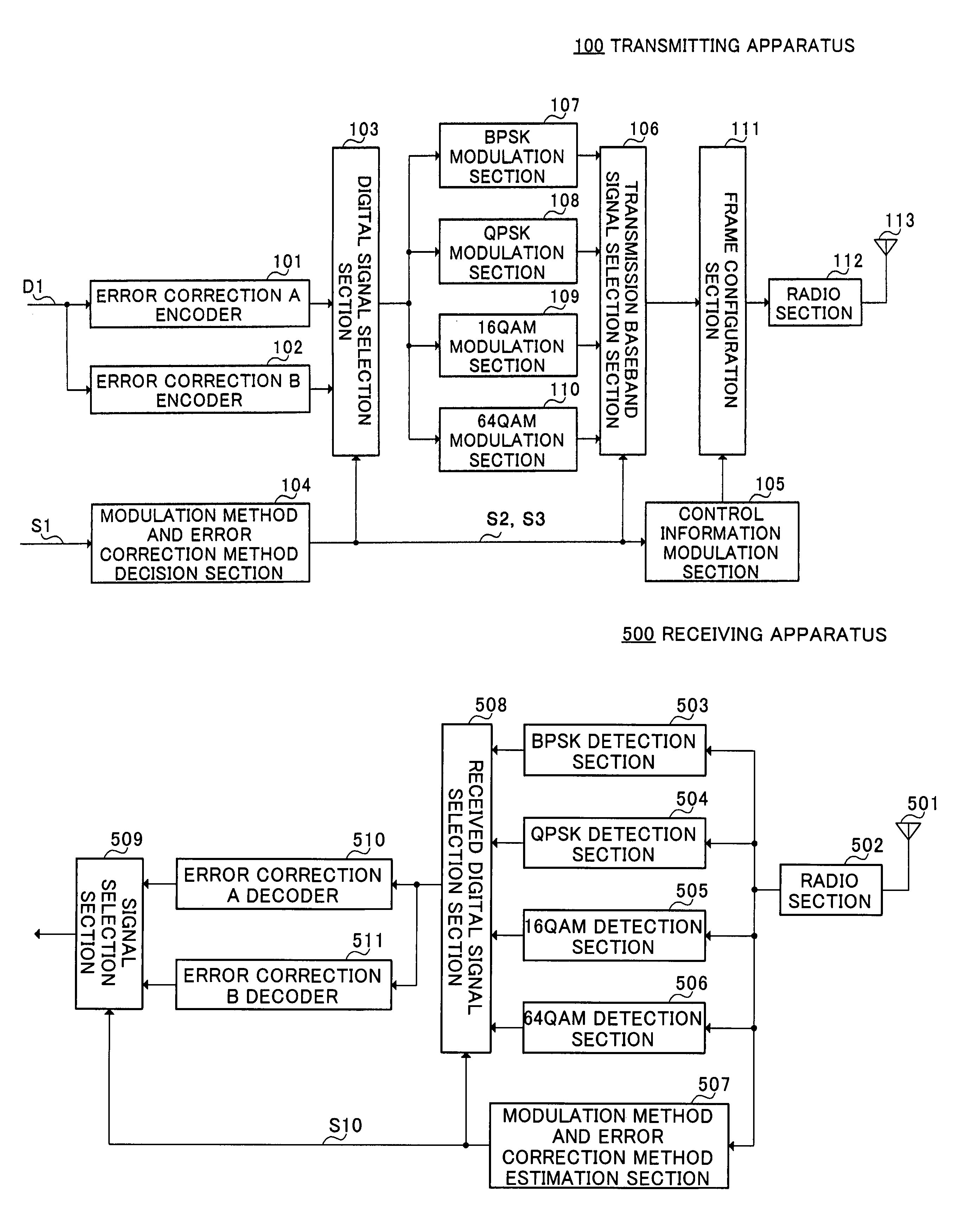
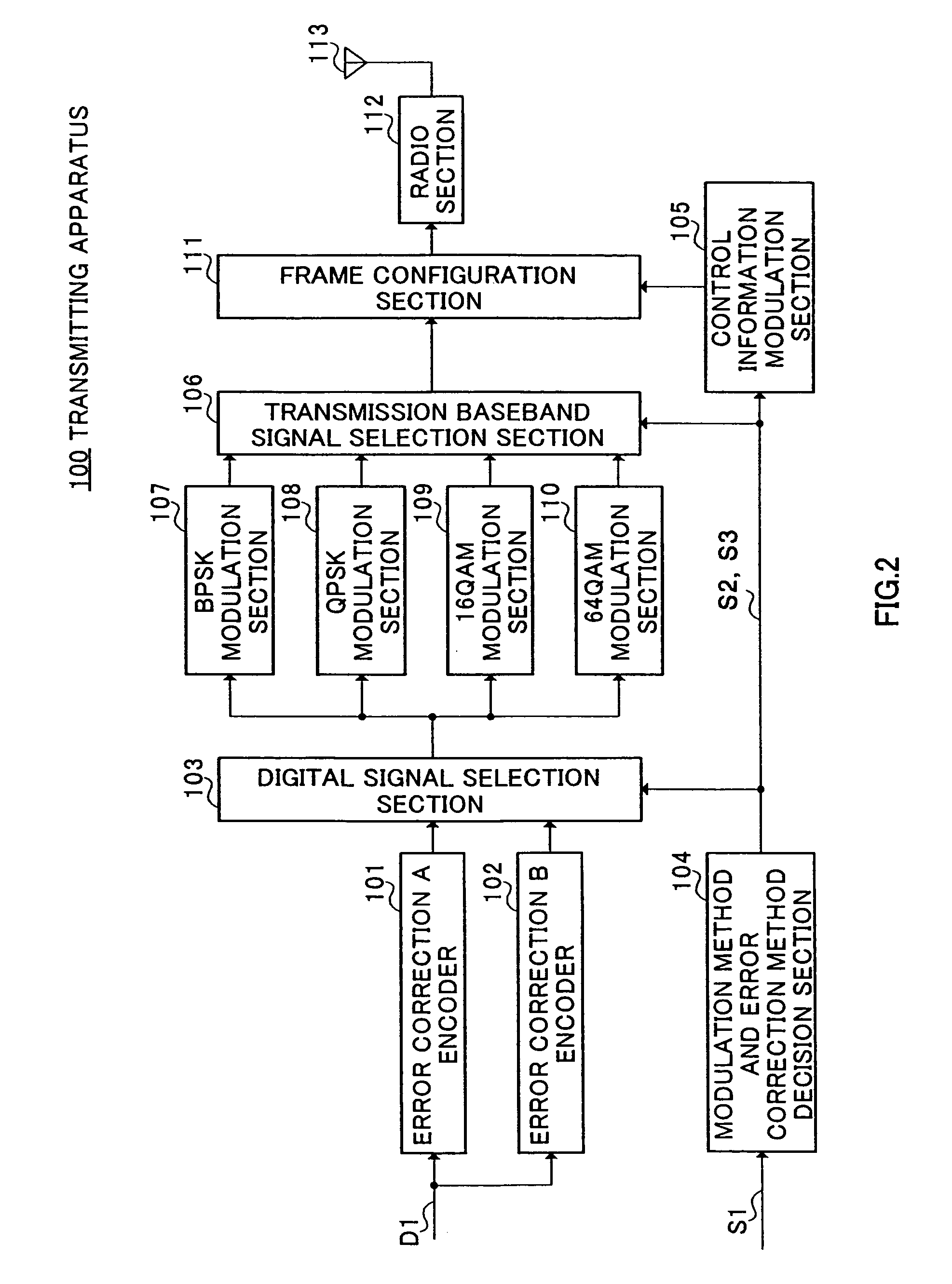
[0025]FIG. 2 shows the configuration of a transmitting apparatus according to Embodiment 1 of the present invention. Transmitting apparatus 100 can select an error correction method and modulation method adaptively according to the state of the propagation path. In transmitting apparatus 100, a transmit digital signal D1 is input to an error correction A encoder 101 and error correction B encoder 102.

[0026]Error correction A encoder 101 and error correction B encoder 102 perform error correction processing with different degrees of redundancy. Specifically, error correction B encoder 102 performs error correction processing with a higher degree of redundancy than error correction A encoder 101, as a result of which error correction B encoder 102 obtains error correction coded data with higher error tolerance. Error correction coded data obtained by error correction A encoder 101 and error correction B encoder 102 is sent to a digital signal selection section 103.

[0027]Transmitting a...

embodiment 2

[0071]FIG. 9, in which parts corresponding to those in FIG. 2 are assigned the same codes as in FIG. 2, shows the configuration of a transmitting apparatus according to Embodiment 2 of the present invention. Transmitting apparatus 800 transmits a transmit signal arranged in a mutually orthogonal plurality of subcarriers by means of OFDM (Orthogonal Frequency Division Multiplexing).

[0072]Specifically, by executing serial / parallel conversion processing on the output of frame configuration section 111 by means of a serial / parallel conversion section (S / P conversion section) 801, and then executing inverse Fourier transform processing on the parallel signals resulting from this processing by means of an inverse Fourier transform section (idft) 802, a transmit signal with the signal arrangement shown in FIG. 10(A) or FIG. 10(B) is formed. Divisions in the frequency direction in FIG. 10(A) and FIG. 10(B) indicate subcarrier demarcations. That is to say, FIG. 10(A) and FIG. 10(B) show exam...


PUM


Abstract

In a communication system in which propagation path error tolerance is improved by switching the modulation method or error correction method adaptively according to the state of the propagation path, signals MX, MY, CX, and CY indicating the modulation method and error correction method used by the transmitting side are transmitted arranged at discrete locations within the same frame. By this means, the possibility of discretely arranged signals MX and MY, or CX and CY, both degrading is made low even if the transmit signal experiences fading or propagation path fluctuations. As a result, it is possible for the modulation method information signal and / or error correction method information signal to be restored correctly on the receiving side.

Description

TECHNICAL FIELD[0001]The present invention relates to a transmitting apparatus, receiving apparatus, transmission method, and reception method, and is suitable for application to a digital radio communication system in which the modulation method or error correction method is changed adaptively according to the propagation path environment, for example.BACKGROUND ART[0002]Conventionally, various kinds of system control are carried out in a radio communication system in order to perform communication with high quality and high efficiency. An example is a radio communication system in which the modulation method or error correction method is switched adaptively according to the state of the propagation path. In this kind of system, the current propagation path state is determined based on the SIR (Signal to Interference Ratio) of a signal that a transmitting / receiving apparatus receives from a communicating party, or the like.[0003]In practice, when the propagation path state is good,...

Claims


Application Information

Patent Timeline
Patent Type & Authority Patents(United States)
IPC IPC(8): G06F11/00H04B14/04H04B14/00H04J11/00H04L1/00H04L27/00
CPCH04L1/0003H04L1/0009H04L1/0025H04L1/0039H04L1/0079H04L27/20H04L27/0008H04L27/0012H04L27/2608H04L1/0083H04L1/0041H04L1/08Y02D30/50H04L5/0044H04L27/18H04L1/0058
Inventor MURAKAMI, YUTAKAABE, KATSUAKIORIHASHI, MASAYUKIMATSUOKA, AKIHIKO
Owner PANASONIC HLDG CORP
Why Eureka
Try Eureka