Method for manufacturing a hollow rack shaft

a manufacturing method and hollow rack technology, applied in forging/pressing/hammering apparatus, television systems, forging/hammering/pressing machines, etc., can solve problems such as large deviation, and achieve the effect of removing elastic deformation

Inactive Publication Date: 2006-07-04
NSK LTD
View PDF42 Cites 5 Cited by
  • Summary
  • Abstract
  • Description
  • Claims
  • Application Information

AI Technical Summary

Benefits of technology

[0023]In addition, when the rack teeth are formed, quite a large amount of material must flow, particularly near the teeth ends of the workpiece W, so a crack 5 may easily be generated at either the cavity 5a or the cavity 5b.
[0031]In the first step of this invention, a first die set is used, wherein the first die set is provided with a surface having a complementary shape to each of the two semi-circular bottom portions in the gutter-like shape, and the surface is inclined in order to eliminate the elastic deformation generated in the workpiece when the workpiece is removed from the first die set.
[0032]In the second step of this invention, a second die set is used, wherein the second die set is provided with a die surface having a complementary shape to a row of rack teeth formed at the flat bottom portion, the surface also having a shape for canceling the elastic deformation of the workpiece when the workpiece is removed from the second die set.

Problems solved by technology

In particular, in a case where a degree of forming is widely different among each of the locations on the workpiece, there is a large amount of deviation.

Method used


Image

  • Method for manufacturing a hollow rack shaft
  • Method for manufacturing a hollow rack shaft
  • Method for manufacturing a hollow rack shaft

Examples


first embodiment

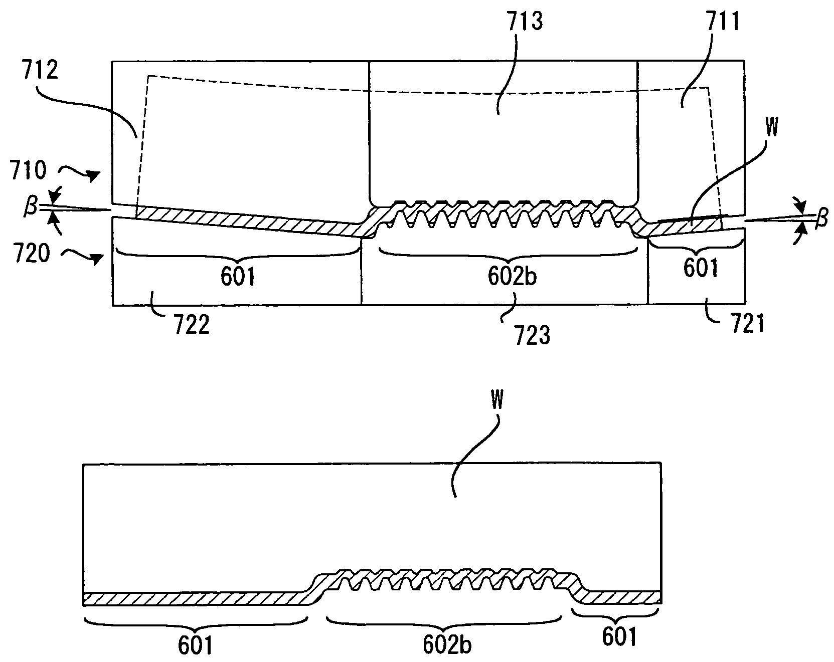
[0064]FIG. 10 is a longitudinal sectional view for showing a flat plate workpiece having been formed into a gutter-like shape (a final end of a press stroke) during the first step of the method of this invention. In the same manner as that of the prior art, upon completion of the first step, the plate workpiece W has a flat bottom at its central portion, and the workpiece is formed into a gutter-like shape including an unformed flat portion 602a in which to form rack teeth during the second step and a semi-circular portion 601 having a semi-circular bottom part. The die set used for this operation is also similar to that of the prior art. Namely, the die set comprises an upper die set 610 including a right upper die 611, a left upper die 612 and a central upper die 613; and a lower die set 620 including a right lower die 621, a left lower die 622 and a central lower die 623.

[0065]However, this invention is different from the prior art in view of the fact that the die surfaces of the...

second embodiment

[0069]In a second step of a second preferred embodiment, the die surface is provided with a recess for releaving an excessive increase in pressure in the die clearance at the end of the stroke of the pressworking. FIG. 14 is a longitudinal section for showing a die set 803 including a central upper die 813 and a central lower die 823 used in the second step, and the workpiece W formed by this die set. It should be noted that FIG. 14 to FIG. 19 are different from FIG. 1 in view of the fact that the upper or lower side of the workpiece W is reversed.

[0070]Each of the central upper die 813 and the central lower die 823 is a split type die composed of a plurality of segments 813S, 823S. Symbols 813D, 823D denote their dividing lines. The extremity of each of the segments 823S has a shape corresponding to one surface of the rack teeth and forms one rack tooth with the same shape of another adjoining segment 823S. Similarly, the extremity of each segment 813S is provided with a shape corr...

third embodiment

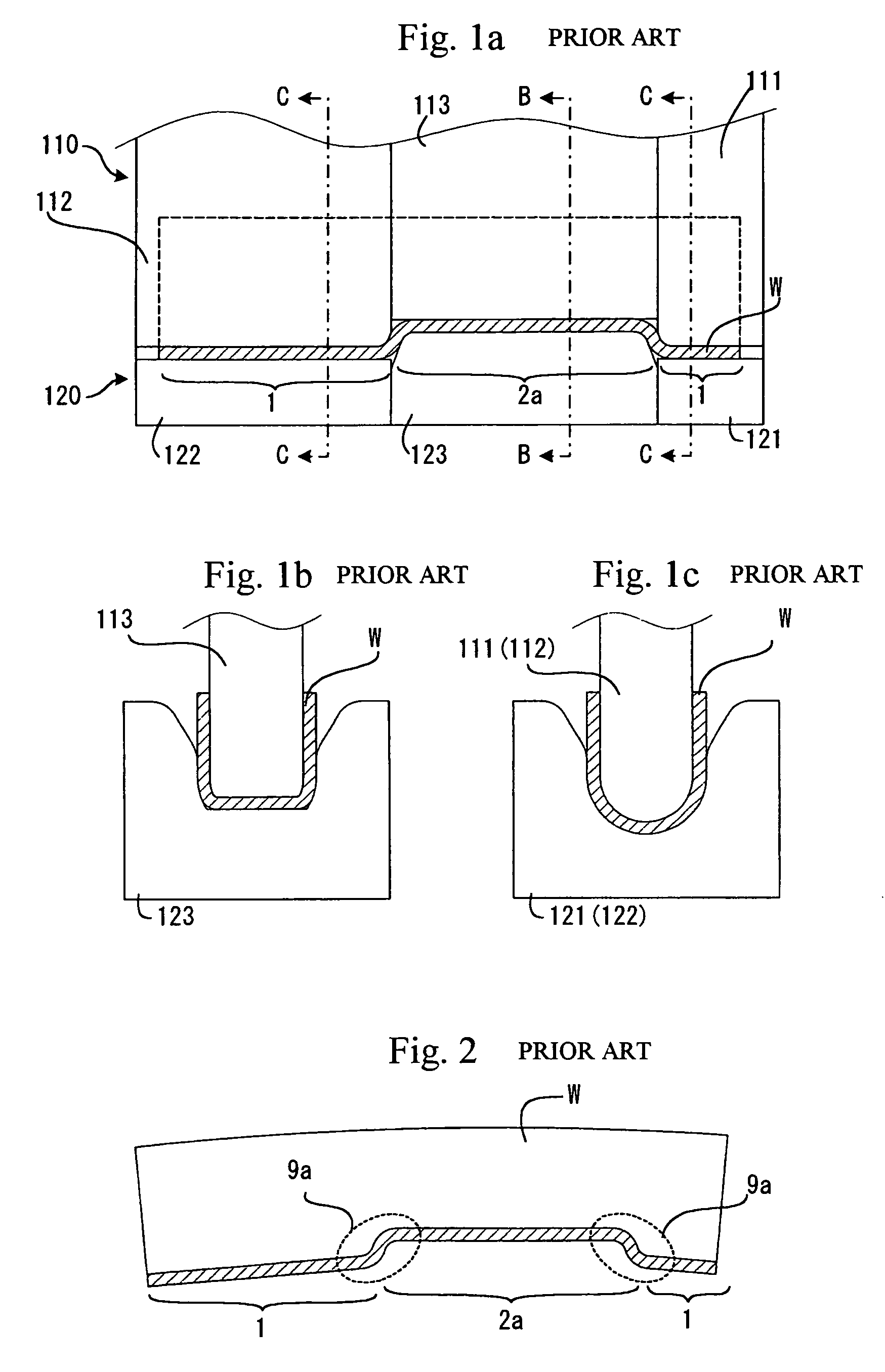
[0080]The aforesaid problem of the third step in the prior art, that is, the back surface of the rack shaft cannot be formed into a true circle, is resolved by using a mandrel as shown in FIGS. 20a to 22c. FIGS. 20a, 21a and 22a are front elevation sectional views; FIGS. 20b, 21b and 22b are sectional views taken along line B—B in each of the front elevation sectional views; and FIGS. 20c, 21c and 22c are sectional views taken along line C—C in each of the front elevation sectional views. The same reference symbols in FIGS. 7a to 9c are used in these figures except for the symbol 112 of the mandrel.

[0081]The workpiece W formed with rack teeth upon completion of the second step is placed on the lower die set 320. At this time, as shown in FIGS. 20a to 20c, the workpiece W is placed such that the two legs 6 are facing up. The upper surface of the central lower die 323 is complementary to the rack tooth shape, and each of the rack teeth is fitted to this complementary rack tooth surfac...


PUM

PropertyMeasurementUnit
elasticaaaaaaaaaa
shapeaaaaaaaaaa
pressing angleaaaaaaaaaa

Abstract

A hollow rack shaft is manufactured through a first step, a second step and a third step. At the first step, the plate-like workpiece of substantial rectangular shape is press formed into a gutter-like shape. The first die set used at this step is provided with slant die surfaces for canceling elastic recovering generated at the workpiece when the workpiece is removed from the first die set. At the second step, a row of rack teeth is press-formed on the flat bottom portion of the workpiece formed in the first step. The die set used at the second step is provided with a recess for releasing surplus workpiece material within the die clearance at a stroke end of the pressworking. At the third step, each of a pair of legs of the workpiece is bent in a semi-circular shape so as to be butted to each other. At this time, a mandrel is inserted between the legs of the workpiece.

Description

[0001]This application is a divisional of U.S. patent application Ser. No. 09 / 803,560, filed Mar. 9, 2001, now U.S. Pat. No. 6,845,560, which is base on Patent Applications No. 2000-64298, No. 2000-114306 and No. 2000-114502 filed in Japan, the contents of which are hereby incorporated by reference.BACKGROUND OF THE INVENTION[0002]1. Field of the Invention[0003]This invention relates to a hollow rack shaft, and more particularly to a method for manufacturing a hollow rack shaft for a steering system used in an automobile.[0004]2. Description of the Related Art[0005]In the case of a rack-and-pinion type steering system for an automobile frequently used in the automotive industry, the rotation of a steering wheel operated by a driver is transmitted to a pinion. The rotation of this pinion is transmitted to a rack shaft engaged with the pinion and this is converted into a motion in a lateral direction (a longitudinal direction of the rack). Since the rack shaft is connected to a steeri...

Claims


Application Information

Patent Timeline
Patent Type & Authority Patents(United States)
IPC IPC(8): B21J13/02B21C37/15B21K1/76B62D3/12
CPCB21C37/155B21K1/063B21K1/767B62D3/126Y10T74/1967Y10T74/19949Y10T29/49467Y10T29/49474Y10T29/49476Y10S72/702
Inventor TSUBOUCHI, AKIRAOKUBO, KIYOSHIWATANABE, YASUSHI
Owner NSK LTD
Why Eureka
Try Eureka