Angular velocity sensor

a technology angular velocity, which is applied in the direction of turn-sensitive devices, instruments, and device material selection, etc., can solve the problems of insufficient startup time reduction, danger of losing the function of angular velocity sensor, and insufficient output voltage of agc circuit, etc., to achieve high stability and precise angular velocity

Inactive Publication Date: 2006-07-04
GYTRONIX
View PDF16 Cites 39 Cited by
  • Summary
  • Abstract
  • Description
  • Claims
  • Application Information

AI Technical Summary

Benefits of technology

[0017]The first aim of the present invention is to provide a highly stable and precise angular velocity sensor that is not influenced by the ambient temperature, the power supply voltage fluctuations and the unevenness in circuit components.
[0018]The second aim of the present invention is to provide an angular velocity sensor that facilitates the temperature compensation, comprised by a semiconductor integrated circuit, and at a reduced production cost.
[0019]The third aim of the present invention is to implement an angular velocity sensor having a stable temperature characteristic even if the piezoelectric vibrator has the large temperature coefficient, and furthermore, to provide a small-sized angular velocity sensor with a relatively simple circuit.

Problems solved by technology

For example, in the case of using the piezoelectric vibrator 1 with a large value of temperature coefficient such as the crystal tuning fork vibrator, an operational range of the AGC circuit inside the oscillator circuit 4 is deviated, and an output voltage of the AGC circuit may be excessive or be insufficient.
There's a danger of losing the function as the angular velocity sensor.
Moreover, the technical problems such as an insufficient reduction in the startup time, an insufficient measure of the startup failure at power ON, a temperature compensation of the Coriolis force detection circuit 5, and a removal of common-mode component, had not been taken into account.

Method used


Image

  • Angular velocity sensor
  • Angular velocity sensor
  • Angular velocity sensor

Examples


first embodiment (fig.2)

First Embodiment (FIG. 2)

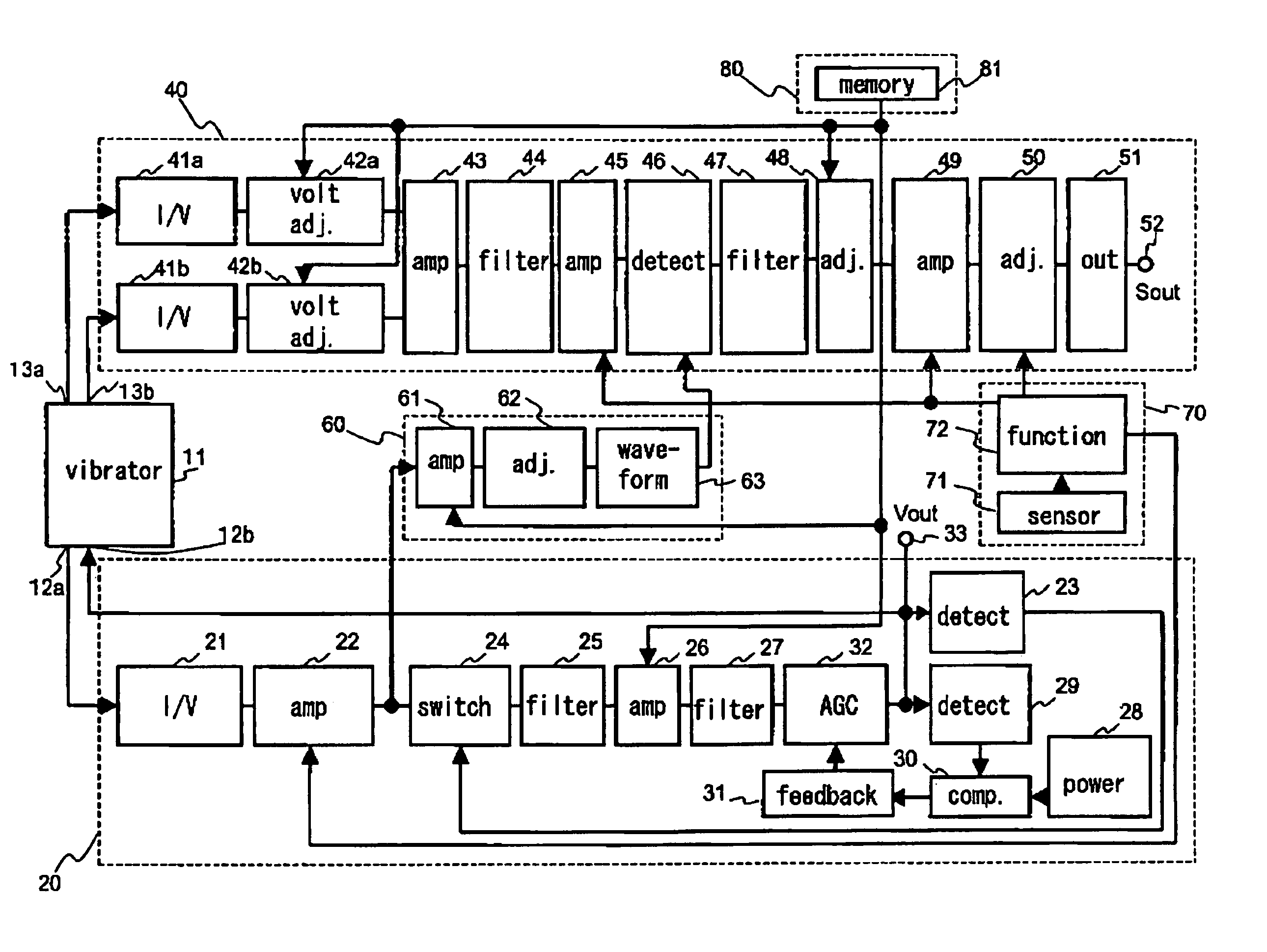
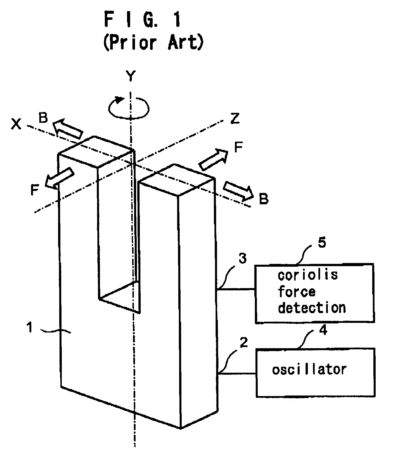
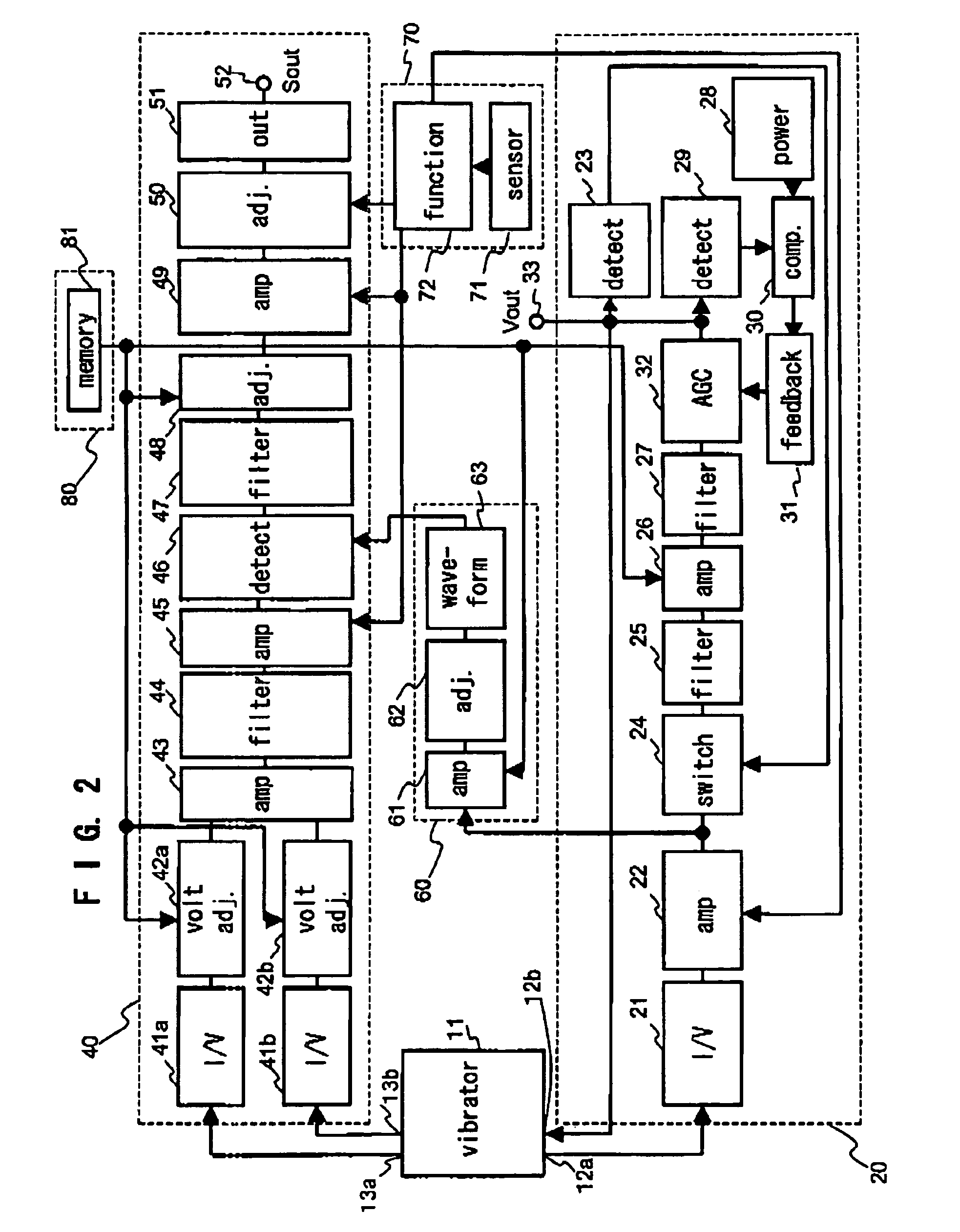
[0047]The angular velocity sensor of FIG. 2, for example, is based on the same principle as the angular velocity sensor of FIG. 1, having the piezoelectric vibrator 11 such as crystal tuning fork vibrator. On the pre-determined positions of the piezoelectric vibrator 11, a first drive electrode 12a and a second drive electrode 12b for driving the piezoelectric vibrator 11, and a first detection electrode 13a and a second detection electrode 13b for detecting an electric charge depending on (for example, proportional to) an angular velocity ω applied to the piezoelectric vibrator 11, are prepared. An oscillator section 20 is connected to the drive electrodes 12a and 12b for supplying an AC drive voltage to the drive electrode 12b, which excites vibration of the piezoelectric vibrator 11 in a specific direction. An Coriolis output detection section 40 is connected to the detection electrode 13a and 13b, for outputting a DC detecting signal S out proportional t...

second embodiment (fig.3)

Second Embodiment (FIG. 3)

[0079]The temperature compensation type amplifier circuit of FIG. 3 is a circuit corresponding to the temperature compensation type amplifier circuit 22 inside the oscillator section 20 and the temperature compensation type amplifier circuit 45 inside the Coriolis output detection section 40 of FIG. 2.

[0080]The temperature compensation type amplifier circuit has an input terminal 101 connected to the output sides of the I / V converter circuit 21 or the high pass filter 44 of FIG. 2. An non-inverting input terminal of an Op amp 102 is connected to the input terminal 101. An output side of the Op amp 102 which is an output terminal 103 is connected to an input side of the gain switching circuit 24 or the synchronous detection circuit 46 of FIG. 2. In between an inverting input terminal of the Op amp 102 and the output side of output terminal 103, one of a feed back resistance 104 is connected. In between the inverting input terminal of the Op amp 102 and a gro...

third embodiment (fig.4)

Third Embodiment (FIG.4)

[0085]A temperature compensation type amplifier circuit shown in FIG.4 corresponds to a circuit of the temperature compensation type amplifier circuit 22 inside the oscillator section 20 or the temperature compensation type amplifier circuit 45 inside the Coriolis output detection section 40 of FIG. 2.

[0086]This temperature compensation type amplifier circuit comprised of Nth inverting amplifier circuits with the identical circuit configuration using Op amps (provided that N is a positive integer no less than 2, for example N=2), and they are serially connected. The first inverting amplifier circuit has an input terminal 111 connected to an output side of the high pass filter 44 or the I / V converter circuit 21 of FIG. 2. On the input terminal 111, an inverting input terminal of the Op amp 113 is connected via one of the feedback resistance 112. In between the inverting input terminal and the output terminal of the Op amp 113, the other feedback resistance 114...


PUM


Abstract

The angular velocity sensor for detecting an angular velocity for detecting movement amounts and for controlling postures of vehicles, airplanes, cameras, and the like. The angular velocity sensor is provided with a piezoelectric vibrator, a temperature compensation function generating section, a correction coefficient setting section, an oscillation section, a synchronous pulse forming section, and a Coriolis output detection section. If an angular velocity is applied to the piezoelectric vibrator vibrating in a specific direction being driven by the oscillator section, a Coriolis force acts on the piezoelectric vibrator, and a vibration is generated which is perpendicular to the vibration in a specific direction. An electric charge generated by this vibration is detected at the detection electrode of the piezoelectric vibrator. The detected electric charge is converted to a voltage at the Coriolis output detection section, and a temperature compensation is performed, and further, the output is detected and a DC component is extracted. After that, a DC detecting signal having high stability without being influenced by factors such as the ambient temperature, power supply voltage fluctuations and unevenness in circuit devices is output from the Coriolis output detection section.

Description

BACKGROUND OF THE INVENTION[0001]1. Field of the Invention[0002]The present invention relates to a stable angular velocity sensor for detecting amount of movements, controlling postures, and the like, which comprises a piezoelectric vibrator, an oscillator section, and a Coriolis output detection section, that are not influenced by factors such as an ambient temperature, power supply voltage fluctuations, and an unevenness in the components, by utilizing the piezoelectric vibrator such as a crystal vibrator.[0003]2. Related Background Art[0004]Conventional technologies related to angular velocity sensors are disclosed in the following patent publications. Examples include Japanese Patent No. 2781161, Japanese Unexamined Patent Publication Nos. HEI 11-44540, 2002-174520, and 2003-87057.[0005]FIG. 1 shows a principle of the angular velocity sensor of the prior art disclosed in Japanese Patent No. 2781161.[0006]For example, if a crystal tuning fork vibrator is used as a piezoelectric v...

Claims


Application Information

Patent Timeline
Patent Type & Authority Patents(United States)
IPC IPC(8): G01P15/00G01C19/56G01C19/5607G01C19/5614G01P15/08H01L41/08H01L41/18
CPCG01C19/5607
Inventor UEHARA, HIRONOBU
Owner GYTRONIX
Why Eureka
Try Eureka