
Pedal device wherein non-operated position of operating portion is adjustable

a pedal device and non-operated technology, applied in the field of pedal devices, can solve the problems of increasing the number of required components and the weight and cost of manufacturing the pedal device, increasing the capacity of the electric motor, and undesirable increases in the structural complexity of the pedal device, so as to reduce the amount of change of the depression resistance force, reduce the weight, and reduce the effect of weigh

Inactive Publication Date: 2006-07-04
TOYODA IRON WORKS CO LTD
View PDF16 Cites 9 Cited by
  • Summary
  • Abstract
  • Description
  • Claims
  • Application Information

AI Technical Summary

Benefits of technology

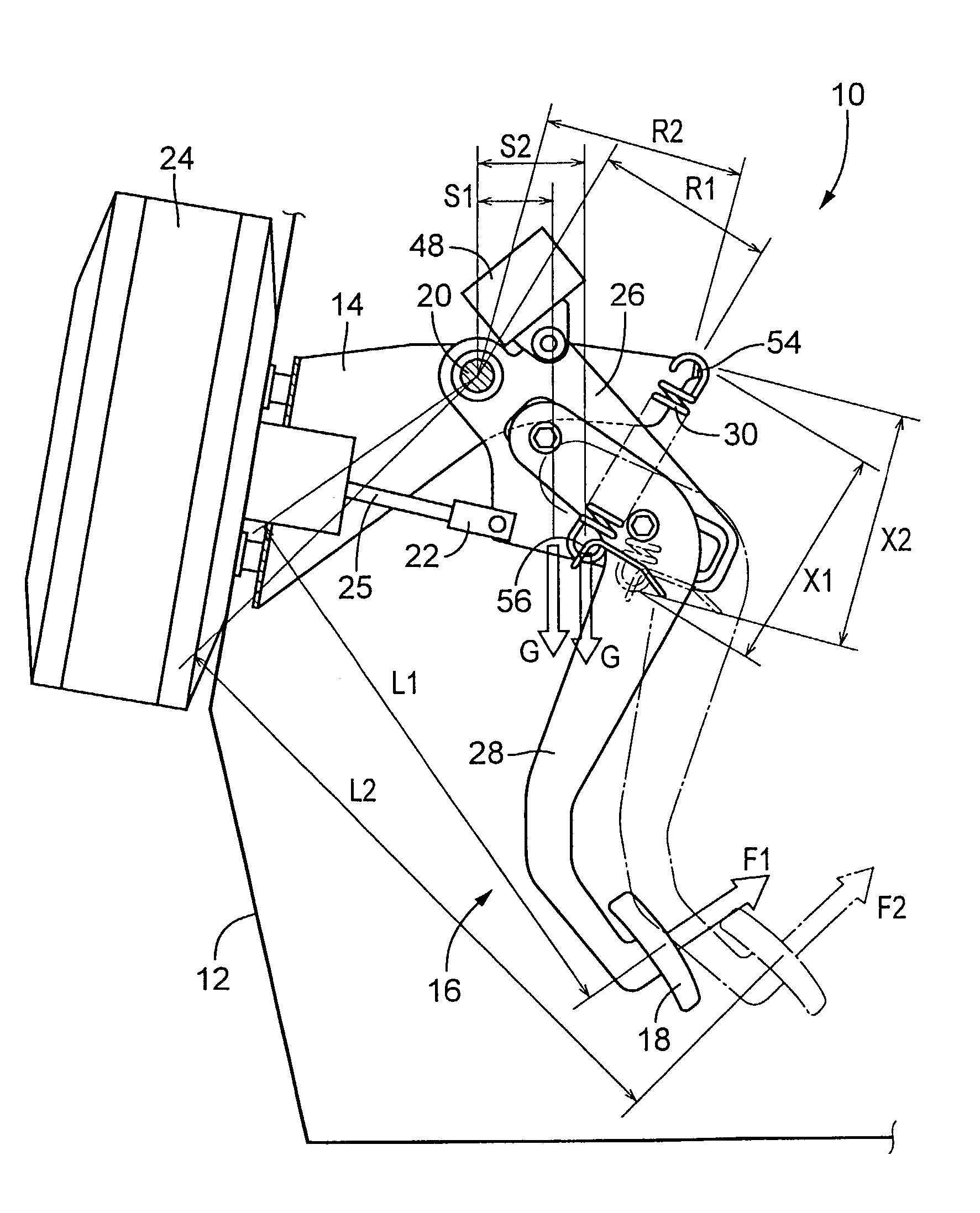
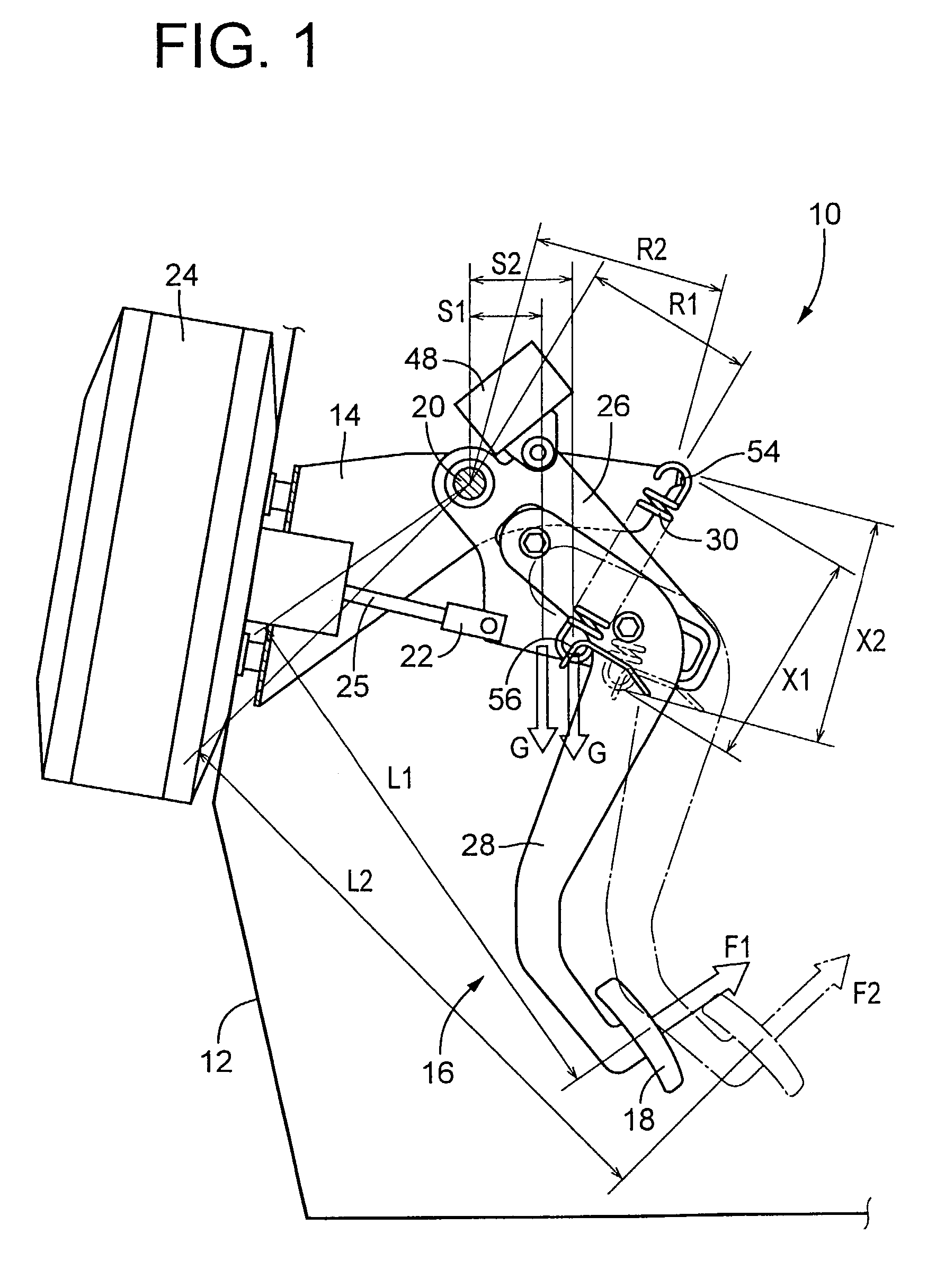
[0007]It is therefore an object of the present invention to provide an adjustable pedal device including a pedal member movable relative to a pivotal member and a mechanism which is arranged to reduce the amount of change of the depression resistance force of the pedal member and which is simple in construction with a reduced weight and economical to manufacture.
[0010]and wherein the return spring is fixed at opposite fixing end portions to the bracket and the pedal member, respectively, positions of the opposite fixing end portions of the return spring relative to the bracket and the pedal member being determined such that a length of an arm of a moment produced by the return spring to bias the pedal in the first direction changes to reduce an amount of change of the above-indicated force of resistance, as the pedal member is moved relative to the pivotal member.
[0013]In the adjustable pedal device constructed according to the above-described mode (1) of the present invention, the return spring is fixed at its opposite fixing end portions to the bracket and the pedal member, respectively, and the positions of the fixing end portions relative to the bracket and the pedal member are determined such that the moment arm length defined as described above changes so as to reduce the amount of change of the force of resistance to the pivotal motion of the pedal in the second direction away from the non-operated position, as the pedal member is moved relative to the pivotal member. Accordingly, the present pedal device does not suffer from an undesirable change of the force of resistance (hereinafter referred to as “depression resistance force”), which change would be felt by the operator of the pedal when the pedal is depressed at its operating portion by the operator.
[0014]Further, a structure or mechanism to maintain the depression resistance force at a substantially constant value irrespective of the relative movement of the pivotal and pedal members is simple in construction with a reduced weight and economical to manufacture. That is, the mechanism is obtained by simply positioning the opposite fixing end portions of the return spring relative to the bracket and the pedal member, respectively, such that the length of the arm of the moment produced by the return spring to bias the pedal member toward the non-operated position changes so as to reduce the amount of change of the depression resistance force. In addition, the change of the length of the arm of the moment reduces the amount of change of the biasing force of the return spring, and is therefore effective to reduce the amount of increase of the resistance to the pivotal motion of the pedal member due to an increase of the biasing force, so that the weight and cost of manufacture of an adjusting device provided to move the pedal member relative to the pivotal member can be significantly reduced. Further, the biasing force of the return spring can be held relatively small, so that the amounts of wear of the related components or portions such as the fixing end portions of the return spring are reduced, so that their required mechanical strength is reduced, and their durability is increased.
[0020]In the adjustable pedal device constructed according to the above mode (4) of the present invention, the positions of the fixing end portions relative to the bracket and the pedal member are determined such that the length of the arm of the moment defined as described above increases with an increase of the lever length between the support shaft and the operating portion of the pedal member, which increase takes place due to a relative movement of the pivotal and pedal members. This arrangement prevents an undesirable change of the depression resistance force, which change would be felt by the operator of the pedal when the pedal is depressed at its operating portion by the operator.
[0022]In the pedal device according to the above mode (5) wherein the adjusting device is provided to move the pedal member relative to the pivotal member while the pedal member is guided by the guiding device, the weight and cost of manufacture of the adjusting device can be reduced, since the length of the arm of the moment produced by the return spring is changed to reduce the amount of increase of the resistance to the pivotal motion of the pedal member due to an increase of the biasing force of the return spring, as described above with respect to the above mode (1).

Problems solved by technology

However, the known adjustable pedal device constructed as described above requires the adjusting lever and the adjusting spring in addition to the return spring, resulting in undesirable increase in the number of the required components and the weight and cost of manufacture of the pedal device, and an undesirable increase in the structural complexity of the pedal device.
Further, an electric motor provided to adjust the pedal is required to pivot also the adjusting lever while elongating or contracting the adjusting spring, so that the required size and capacity of the electric motor are increased, resulting in a further increase in the weight and cost of manufacture of the pedal device.

Method used


Image

  • Pedal device wherein non-operated position of operating portion is adjustable
  • Pedal device wherein non-operated position of operating portion is adjustable
  • Pedal device wherein non-operated position of operating portion is adjustable

Examples


Embodiment Construction

[0034]Referring to first to the partly cut-away side elevational view of FIG. 1, there is shown an adjustable pedal device in the form of a brake pedal device 10 which is constructed according to one embodiment of this invention and installed on an automotive vehicle. In FIG. 1, the left portion of the view corresponds to the front side of the vehicle, while the right side portion corresponds to the rear side of the vehicle. Namely, a vehicle operator's seat is located on the right side of the elevational view of FIG. 1. The brake pedal device 10 is mounted on a bracket 14 fixed on a body 12 (e.g., a dash panel) of the vehicle, and includes a brake pedal 16 having an operating portion in the form of a pedal pad 18 at its lower end. When the brake pedal 16 is depressed at its pedal pad 18 while the brake pedal 16 is placed at the presently selected non-operated or original position of FIG. 1, the brake pedal 16 is pivoted clockwise (as seen in FIG. 1) about a support shaft 20 fixedly...


PUM


Abstract

An adjustable pedal device including (a) a support shaft fixedly disposed on a bracket, (b) a pedal including a pivotal member and a pedal member, and a return spring interposed between the bracket and the pedal member, and wherein the pivotal member is pivotable about the support shaft, while the pedal member is movable relative to the pivotal member to a selected one of a plurality of relative positions, and has at its lower end an operating portion at which the pedal member is operated so that the pedal member and the pivotal member are pivoted together about the support shaft, the return spring biasing the pedal member so as to pivot the pedal about the support shaft in a first direction toward a non-operated position of the pedal, and producing a force of resistance to a pivotal motion of the pedal in a second direction away from the non-operated position when the pedal is operated, and wherein the positions of opposite end portions of the return spring at which the spring is fixed to the bracket and the pedal member are determined such that a length of an arm of a moment produced by the spring to bias the pedal in the first direction changes so as to reduce an amount of change of the force of resistance, as the pedal member is moved relative to the pivotal member.

Description

[0001]This application is based on Japanese Patent Application No. 2002-246783 filed Aug. 27, 2002, the contents of which are incorporated hereinto by reference.BACKGROUND OF THE INVENTION[0002]1. Field of the Invention[0003]The present invention relates in general to a pedal device such as a brake pedal device and an accelerator pedal device, and more particularly to an improved adjustable pedal device wherein the non-operated position of an operating portion of a pedal is adjustable.[0004]2. Discussion of Related Art[0005]There is known an adjustable pedal device having a pedal including (a) a pivotal member which is supported by a bracket such that the pivotal member is pivotable about a support shaft, and (b) a pedal member disposed movably relative to the pivotal member to a selected one of a plurality of relative positions and having at its lower end an operating portion at which the pedal member is operated so that the pedal member and the pivotal member are pivoted together ...

Claims


Application Information

Patent Timeline
Patent Type & Authority Patents(United States)
IPC IPC(8): G05G1/30B60K26/02B60T7/06G05G1/40G05G1/405G05G7/04
CPCG05G1/405Y10T74/20528
Inventor HAYASHIHARA, TAKASHI
Owner TOYODA IRON WORKS CO LTD
Learn More