Filler

a technology of a filter and a filter body, applied in the field of filters, can solve the problems of increased cost, large space for its provision, complex and bulky apparatus, etc., and achieve the effects of reducing sampling time, reducing cost, and simplifying construction

Active Publication Date: 2006-07-04
SHIBUYA IND CO LTD
View PDF10 Cites 10 Cited by
  • Summary
  • Abstract
  • Description
  • Claims
  • Application Information

AI Technical Summary

Benefits of technology

[0005]Accordingly, it is an object of the present invention to provide a filler which is simple in construction and enables a sampling operation to be completed in a reduced length of time while avoiding the need to extract a vessel from the line on which vessels are conveyed and filled.
[0007]With the described arrangement according to the present invention, there is no need to measure a vessel by extracting it from the line on which vessels are conveyed on a filler, and there is no need to return the vessel to the line also, thus dispensing with an apparatus such as a gripper which performs these operations and simplifying the construction to allow a reduction in the cost required. In addition, there is no need to repeat a sampling operation a number of times equal to the number of nozzles, and vessels which are concurrently filled by a plurality of nozzles can be sampled in one operation, allowing a substantial reduction in the sampling time.

Problems solved by technology

In the arrangement of the sampler disclosed in the citation, there is a need for an apparatus which extracts a vessel from the production line on which vessels are conveyed and filled and returns it to the line after measuring the weight, with consequent problems that the apparatus becomes complex and bulky, requiring a large space for its provision and resulting in an increased cost.
Another problem arises also that the sampling operation must extract and return a vessel from and to the line and thus takes a time.
In particular, in an arrangement where a plurality of vessel are conveyed intermittently and are filled concurrently, the sampling operation must be repeated a number of times equal to the number of the nozzles, resulting in a prolonged length of time required for the sampling operations.

Method used


Image

  • Filler
  • Filler
  • Filler

Examples


Embodiment Construction

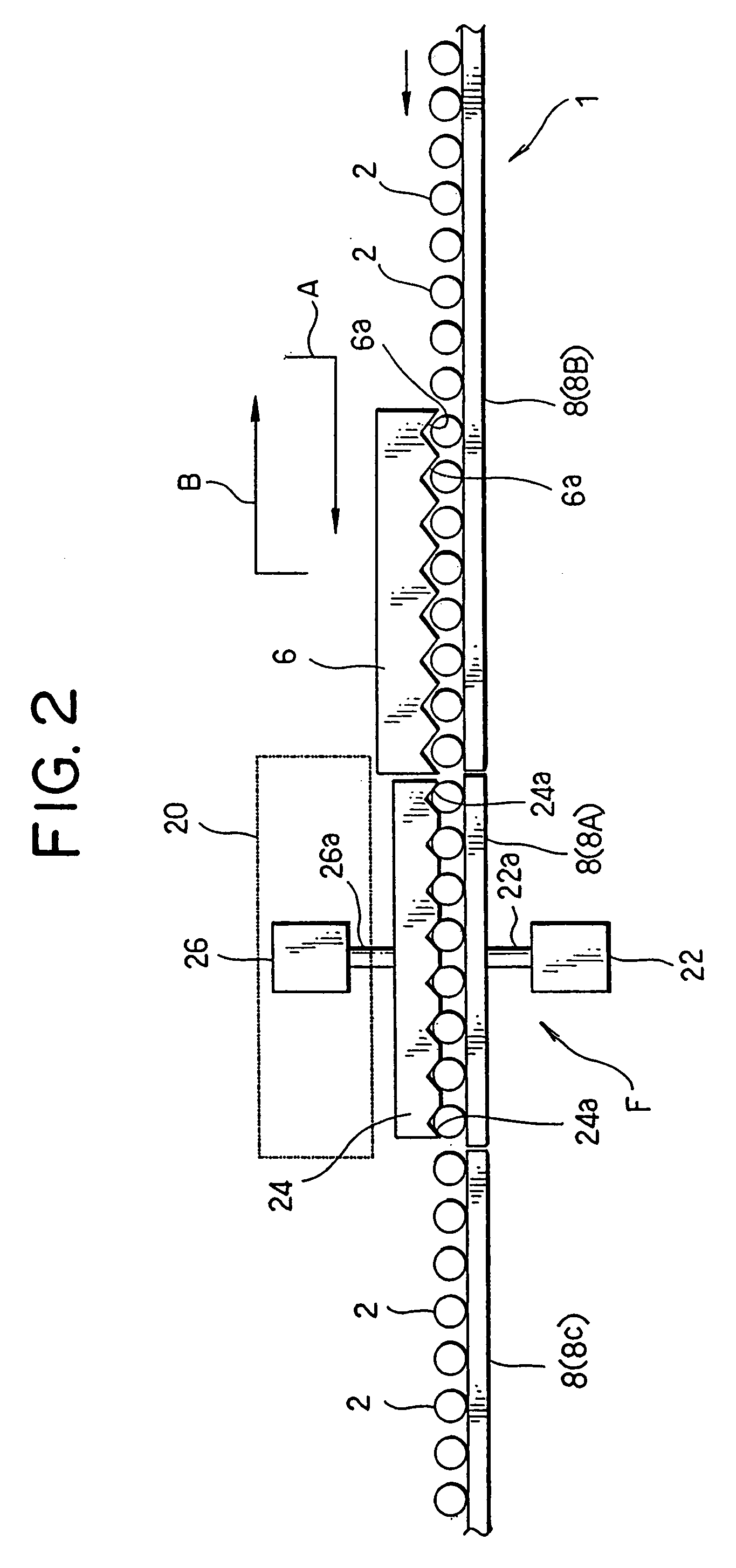
[0013]A vessel conveying line (generally indicated by numeral 1) which conveys a number of vessels 2 in one row comprises a conveying rail 4 (omitted from illustration in FIG. 2) which supports bottom surfaces of the vessels 2, a transfer rake 6 which engages vessels 2 placed on the conveying rail 4 for advancing them intermittently, and a back guide 8 which supports barrels of the vessels 2 from the back side as the vessels 2 are advanced by the transfer rake 6. The transfer rake 6 can reciprocate along the traveling direction of the vessels 2 (or movement in directions to the left and to the right as viewed in FIG. 2) and is also moveable back and forth toward the vessels 2 on the vessel conveying line 1 (or vessels 2 on the conveying rail 4) (movement in the vertical direction as viewed in FIG. 2). It moves toward the conveying rail 4 from a position where it is retracted from the conveying line 1 to engage the vessels 2, and move downstream to convey the vessels 2 (see arrow A s...


PUM

PropertyMeasurementUnit
weightaaaaaaaaaa
pressureaaaaaaaaaa
timeaaaaaaaaaa

Abstract

Vessels 2 on a conveying rail 4 are supported by a back guide 8 and are intermittently conveyed by a transfer rake 6. A number of filling nozzles 28 which corresponds to a number of vessels 2 are installed at a filling station F, and the conveying rail has a portion 4A which is elevatable. Metering receptacles 12 connected to load cells 16 are disposed in a manner corresponding to respective filling nozzles 28. These metering receptacles 12 do not contact vessels 2 when the conveying rail portion 4A is raised, but support the vessels when the conveying rail portion 4A is lowered, allowing a mensuration of the weight of vessels 2 by the load cells 16. During a normal filling operation, the conveying rail portion 4A is maintained in its raised position to convey the vessels 2 and performs a filling operation. During a sampling operation, the conveying rail portion 4A is lowered to place vessels 2 on the metering receptacles 12 to perform a mensuration while performing a filling operation. A sampling operation can be performed in a reduced length of time using a simple construction.

Description

BACKGROUND OF THE INVENTION AND RELATED ART STATEMENT[0001]The present invention relates to a filler, in particular, to a filler provided with a sampling mechanism.[0002]A filler is usually designed to open a liquid valve in a filled liquid passage formed within a filling valve to allow a liquid fed from a filled liquid tank to be filled into a vessel and to terminate a filling operation by closing the liquid valve upon detecting by metering means that a given quantity of filled liquid has been filled. In such a filler, a weight which is filled into the vessel is determined by a sampling test in order to confirm the accuracy of a filling operation for each filling valve. A filler which is provided with such a sampling mechanism is already known in the art (see, for example, Japanese Laid-Open Patent Publication No. 2002-362502).[0003]A sampler disclosed in this citation is installed in a filler in which conveying means convey vessels one after another to a filling position where a f...

Claims


Application Information

Patent Timeline
Patent Type & Authority Patents(United States)
IPC IPC(8): B65B1/04
CPCB65B3/28B67C3/202G01G15/00G01F13/006G01G13/02B67C7/0033
Inventor KAKUDA, MASANORI
Owner SHIBUYA IND CO LTD
Why Eureka
Try Eureka