Light source device and display device

a technology of light source and display device, which is applied in the direction of fixed installation, lighting and heating apparatus, instruments, etc., can solve the problem of extremely short operation life of discharge tube, and achieve the effect of long operation li

Inactive Publication Date: 2006-07-04
FUJITSU LTD
View PDF8 Cites 24 Cited by
  • Summary
  • Abstract
  • Description
  • Claims
  • Application Information

AI Technical Summary

Benefits of technology

[0005]The object of the present invention is to provide a light source device capable of a long operational life of a discharge tube.
[0006]A light source device, according to the first aspect of the present invention, comprises a discharge tube, a reflector for reflecting a light radiated from the discharge tube, and support members for supporting the discharge tube to the reflector, said support members being formed of a heat insulating structure so as to prevent a temperature drop of a portion of the discharge tube near electrodes of the discharge tube.
[0007]A light source device, according to the second aspect of the present invention, comprises a discharge tube, a reflector for reflecting a light radiated from the discharge tube, and support members for supporting the discharge tube to the reflector, the discharge tube being formed of a partially heat insulating structure so as to prevent a temperature drop of a portion of the discharge tube near electrodes of the discharge tube.
[0008]A light source device, according to the third aspect of the present invention, comprises a discharge tube, a reflector for reflecting a light radiated from the discharge tube, and support members for supporting the discharge tube to the reflector, the support members being arranged at positions inward from ends of electrodes of the discharge tube so as to prevent a temperature drop of a portion of the discharge tube near electrodes of the discharge tube.
[0012]Mercury exists in the discharge tube in a gaseous state as well as in a non-gaseous state (liquid or solid). The liquid mercury is collected at the lowest temperature point in the discharge tube (because a concentration gradient is produced because of a difference in a saturated vapor pressure due to a temperature difference, mercury is conveyed by diffusion). Particles of metal of the electrodes caused by sputtering with electrons are deposited on the thus collected liquid mercury, and produces a thin membrane on the liquid mercury. This membrane prevents the mercury from evaporating, and the amount of the gaseous mercury in the discharge tube is reduced. If the amount of the gaseous mercury is reduced, the discharge tube becomes dark and the operating life thereof is short.
[0013]Accordingly, in the present invention, a shortened operational life of the discharge tube is prevented by adopting the above-described arrangements so that the portion of the discharge tube near the electrodes of the discharge tube does not become the lowest temperature point and so that the liquid mercury is not captured and enclosed by the particles of metal of the sputtered electrodes, whereby the amount of the gaseous mercury is not reduced.

Problems solved by technology

Usually, a sufficient amount of mercury gas is sealed in the discharge tube to enable the discharge tube to have a long life, but there are discharge tubes having extremely short operational lives.

Method used


Image

  • Light source device and display device
  • Light source device and display device
  • Light source device and display device

Examples


Embodiment Construction

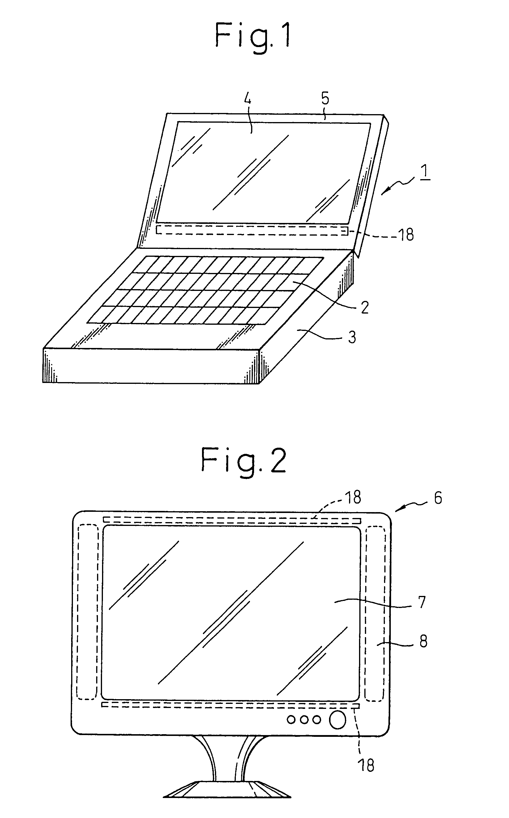
[0034]Embodiments of the present invention will be explained hereinafter with reference to the accompanying drawings. FIG. 1 is a view showing the notebook type personal computer including the light source device according to the embodiment of the present invention, and FIG. 2 is a view showing the display device including the light source device according to the present invention.

[0035]In FIG. 1, the notebook type personal computer 1 comprises a body 3 having a keyboard 2 and electronic circuits, and a display part 5 having a display 4 such as a liquid crystal display device. The display part 5 has a light source device 18. The notebook type personal computer 1 of FIG. 1 includes one light source device 18, but it is possible to arrange two light source devices 18, as in the case of the display device 6 of FIG. 2.

[0036]In FIG. 2, the display device 6 comprises a body 8 having a display 7 such as a liquid crystal display device and electronic circuits. The body 8 has light source de...


PUM

PropertyMeasurementUnit
diameteraaaaaaaaaa
diameteraaaaaaaaaa
temperatureaaaaaaaaaa

Abstract

A light source device includes a discharge tube, a reflector for reflecting a light radiated from the discharge tube, and support members for supporting the discharge tube to the reflector. The support member or the discharge tube is formed of a heat insulating structure so as to prevent a temperature drop of a portion of the discharge tube near electrodes thereof. By this arrangement, it is possible to prolong the operational life of the discharge tube.

Description

CROSS REFERENCE TO RELATED APPLICATION[0001]This application is a continuation of PCT / JP 02 / 02622 filed Mar. 19, 2002, which claims the priority of Japanese Application No. 2001-078546 filed Mar. 19, 2001, which is incorporated herein by reference.TECHNICAL FIELD[0002]The present invention relates to a light source device having a discharge tube emitting light by a discharge in a lean gas.BACKGROUND ART[0003]A backlight, as a light source device of a display device such as a liquid crystal display device, uses a light source device comprising one or a plurality of discharge tubes and a reflector. The discharge tube is a cold cathode tube, in which mercury is contained in a lean gas (such as Ar and Ne) and a fluorescent material is coated on the tube wall. Electrodes are provided in both ends of the discharge tube. The discharge tube is supported by the reflector with support members which are arranged at positions near the electrodes of the discharge tube. The backlight also has a l...

Claims


Application Information

Patent Timeline
Patent Type & Authority Patents(United States)
IPC IPC(8): F21V15/06F21S2/00F21V7/00F21V8/00F21V19/00F21V29/15F21V29/505F21Y101/00G02F1/13357H01J61/52H01J61/72
CPCF21V29/004F21V29/85H01J61/523H01J61/72F21V29/15F21V19/009G02F1/133604G02F1/133608G02F2001/133628G02F1/133628G02F1/1335
Inventor SOTOKAWA, AKIOHACHISUKA, SEIJI
Owner FUJITSU LTD
Why Eureka
Try Eureka