Electrical connector assembly having reinforcing mechanism

a technology of electrical connectors and reinforcing mechanisms, which is applied in the direction of electrical discharge lamps, electrical device connections, electrical apparatus construction details, etc., can solve the problems of increased complexity, unwound, and higher manufacturing costs, and achieve the effect of ensuring mechanical and electrical characteristics of the electrical connector assembly

Inactive Publication Date: 2006-07-04
HON HAI PRECISION IND CO LTD
View PDF7 Cites 13 Cited by
  • Summary
  • Abstract
  • Description
  • Claims
  • Application Information

AI Technical Summary

Benefits of technology

[0012]Accordingly, a primary object of the present invention is to provide an electrical connector assembly with a reinforcing mechanism, to reinforce a socket body and relieve tensile forces resulted between the socket body and the soldering balls during assembly or installation.
[0014]Via engagement between the protrusions of the socket body and the respective slots of the frame, the tensile forces between the socket body and the soldering balls are remarkably relieved. Thus the socket body is effectively reinforced and mechanical and electrical characteristics of the electrical connector assembly are ensured.

Problems solved by technology

These will result in increased complexity and higher cost of manufacture and are not desired.

Method used


Image

  • Electrical connector assembly having reinforcing mechanism
  • Electrical connector assembly having reinforcing mechanism
  • Electrical connector assembly having reinforcing mechanism

Examples


Embodiment Construction

[0021]Reference will now be made to describe the present invention in detail.

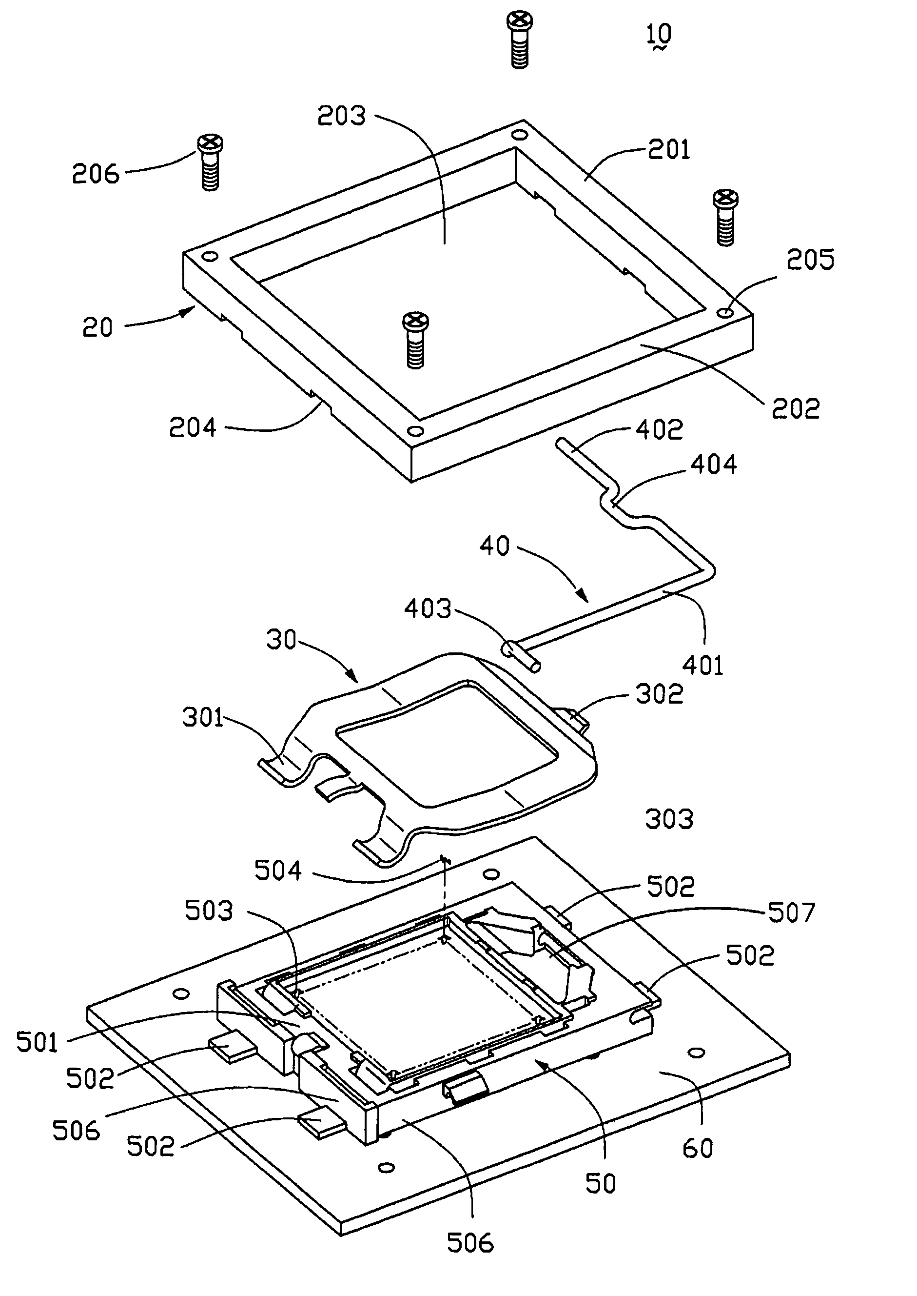
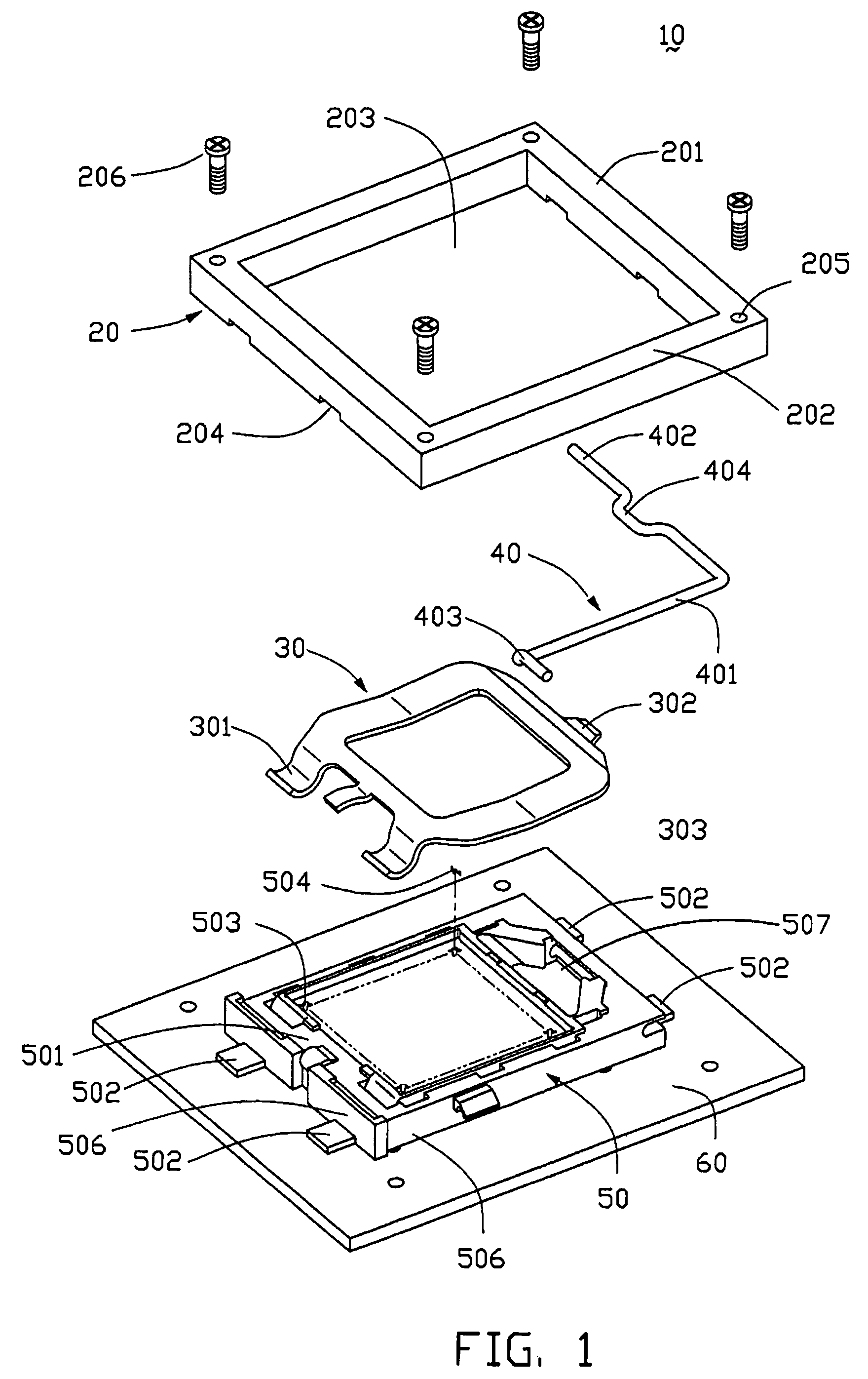
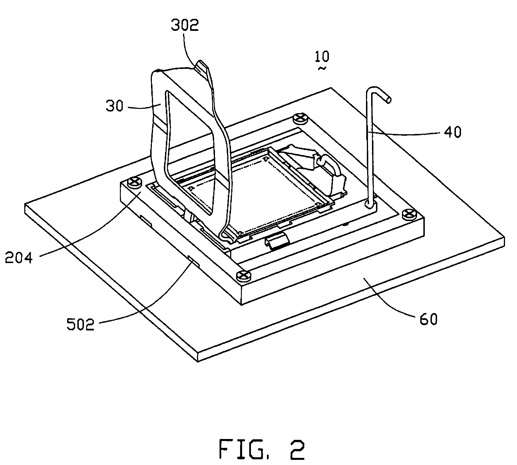
[0022]FIGS. 1–3 show an electrical connector assembly 10 in accordance with a preferred embodiment of the present invention, for electrically connecting an IC package with a PCB. The electrical connector assembly 10 includes a substantially rectangular socket body 50, a frame 20 arranged around the socket body 50, and a socket plate 30 and a load lever 40 mounted to opposite ends of the socket body 50.

[0023]The socket body 50 includes a plurality of first sidewalls 505, 506. The first sidewalls 505, 506 cooperatively form a planar configuration to hold the IC package (not shown) thereon. The socket body 50 forms a connecting section 501 to pivotally accommodate the socket plate 30, and a retaining section 507 opposite to the connecting section 501, to receive the load lever 40. The load lever 40 rotates around an axis to press or release the socket plate 30. A plurality of protrusions is formed on exterior ...


PUM


Abstract

An electrical connector assembly (10) includes a socket body (50), a frame (20) arranged around the socket body, and a socket plate (30) and a load lever (40) mounted to opposite ends of the socket body respectively. The socket body has a number of first sidewalls (505, 506). The first sidewalls form a number of protrusions (502) distant from a center of the socket body on exterior surfaces. The frame includes a number of second sidewalls (201, 202). The second sidewalls correspondingly define a number of slots (204) to mate with the respective protrusions. Via engagement between the protrusions and the corresponding slots, the frame can press down the socket body and prevent opposite ends of the socket body from bending upward, thereby reinforcing the socket body.

Description

BACKGROUND OF THE INVENTION[0001]1. Field of the Invention[0002]The present invention relates to electrical connector assemblies, and more particularly, to an electrical connector assembly having reinforcing mechanism for electrically connecting two electrical interfaces, such as an integrated circuit (IC) package and a printed circuit board (PCB).[0003]2. Description of the Prior Art[0004]An electrical connector assembly is commonly used to route signal and power between two electrical interfaces, such as an IC package and a PCB. Normally, an electrical connector assembly comprises a socket body, a frame set around the socket body, and a plurality of contacts received in the socket body. Each contact includes a spring arm and a soldering section protruding beyond two opposite external surfaces of the socket body. In installation, the spring arm is resiliently urged to electrically engage the IC package. The soldering section is connected to a respective conductive pad arranged on t...

Claims


Application Information

Patent Timeline
Patent Type & Authority Patents(United States)
IPC IPC(8): H01R13/625H01R13/187H01R33/76
CPCH05K7/1061
Inventor CHIN, CHING-KUO
Owner HON HAI PRECISION IND CO LTD
Why Eureka
Try Eureka