Multi-hull watercraft with amidships-mounted propellers

a propeller and multi-hull technology, applied in the field of multi-hull watercraft with amidships-mounted propellers, can solve problems such as fault tolerance of watercraft, and achieve the effect of avoiding some of the costs and disadvantages

Active Publication Date: 2006-07-04
LOCKHEED MARTIN CORP
View PDF10 Cites 4 Cited by
  • Summary
  • Abstract
  • Description
  • Claims
  • Application Information

AI Technical Summary

Benefits of technology

[0004]The present invention is particularly well-suited with double-ended watercraft and avoids some of the costs and disadvantages associated with double-ended watercraft in the prior art. Although the illustrative embodiment of the present invention is a double-ended watercraft, it will be clear to those skilled in the art, after reading this specification, how to make and use embodiments of the present invention in other watercraft and machines, such as aircraft, windmills, and axial impellers for ventilation and other air handling applications such as wind tunnels.
[0006]Each hull comprises an independent engine and gearbox that drives a propeller shaft and propeller that is located amidships. Mounting the propellers amidships is advantageous because it reduces the propellers vulnerability to ice, grounding in shallow water, and other impediments.
[0007]The propeller shafts on the starboard are collinear, as are the propeller shafts on the port. The propellers on the starboard oppose each other and counter rotate, as do the propellers on the port, and form a counter-rotating propeller system. This affords the advantages of a counter-rotating propeller system without the disadvantage of counter-rotating propeller systems in the prior art (e.g., counter-rotating concentric shafts, complex gear boxes, etc.). Having two independent engines / gearboxes / propeller shafts / shafts on both the port and starboard also provides redundancy, which makes the craft fault-tolerant.
[0008]In accordance with the illustrative embodiment, the propellers are variable-pitch propellers. When the ferry changes from moving forward to moving in reverse and from reverse to forward, the pitch and the direction of rotation of each propeller changes. This enables the ferry to move as efficiently in reverse as it does when forward.

Problems solved by technology

Having two independent engines / gearboxes / propeller shafts / shafts on both the port and starboard also provides redundancy, which makes the craft fault-tolerant.

Method used


Image

  • Multi-hull watercraft with amidships-mounted propellers
  • Multi-hull watercraft with amidships-mounted propellers
  • Multi-hull watercraft with amidships-mounted propellers

Examples


Embodiment Construction

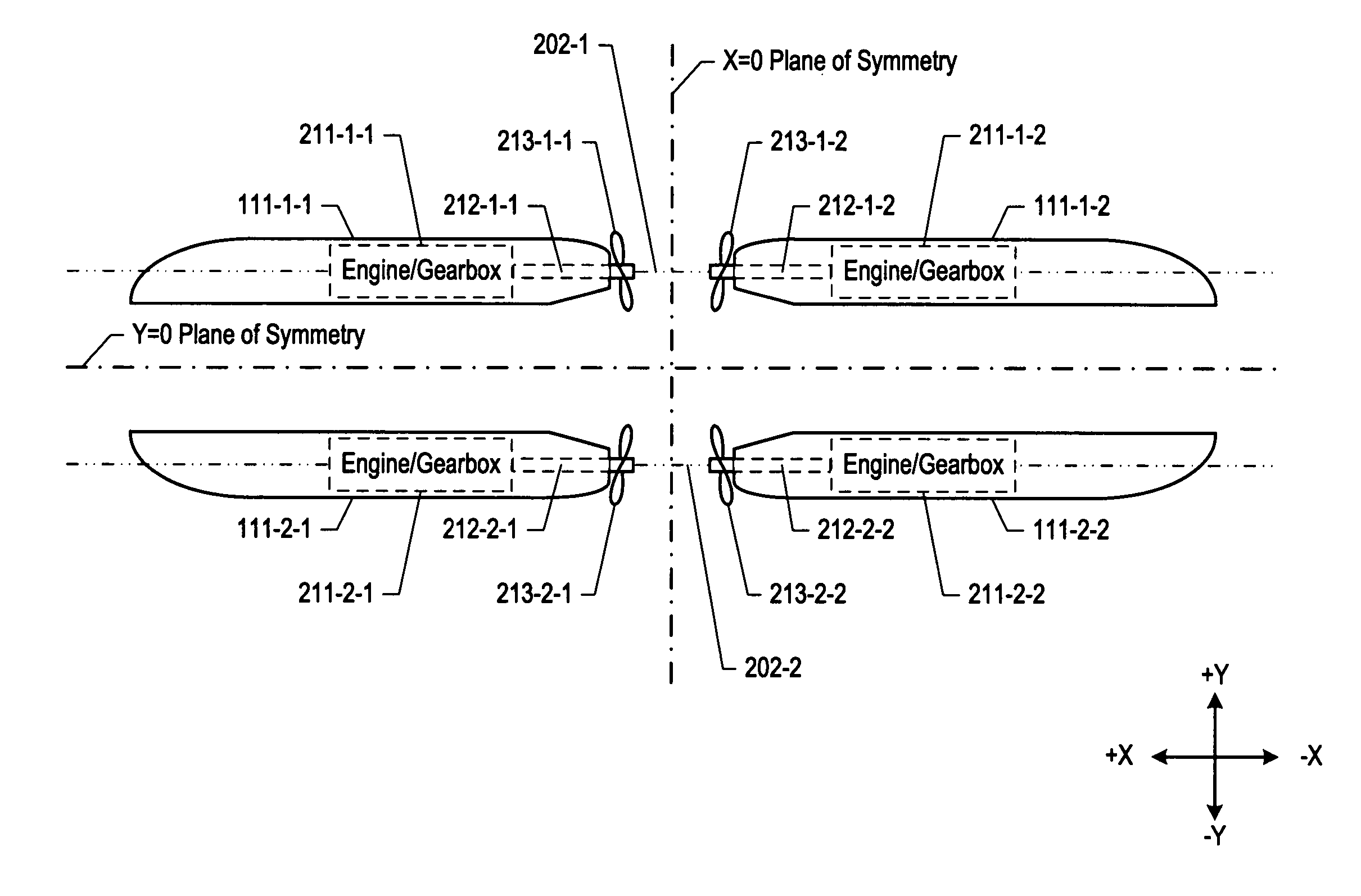
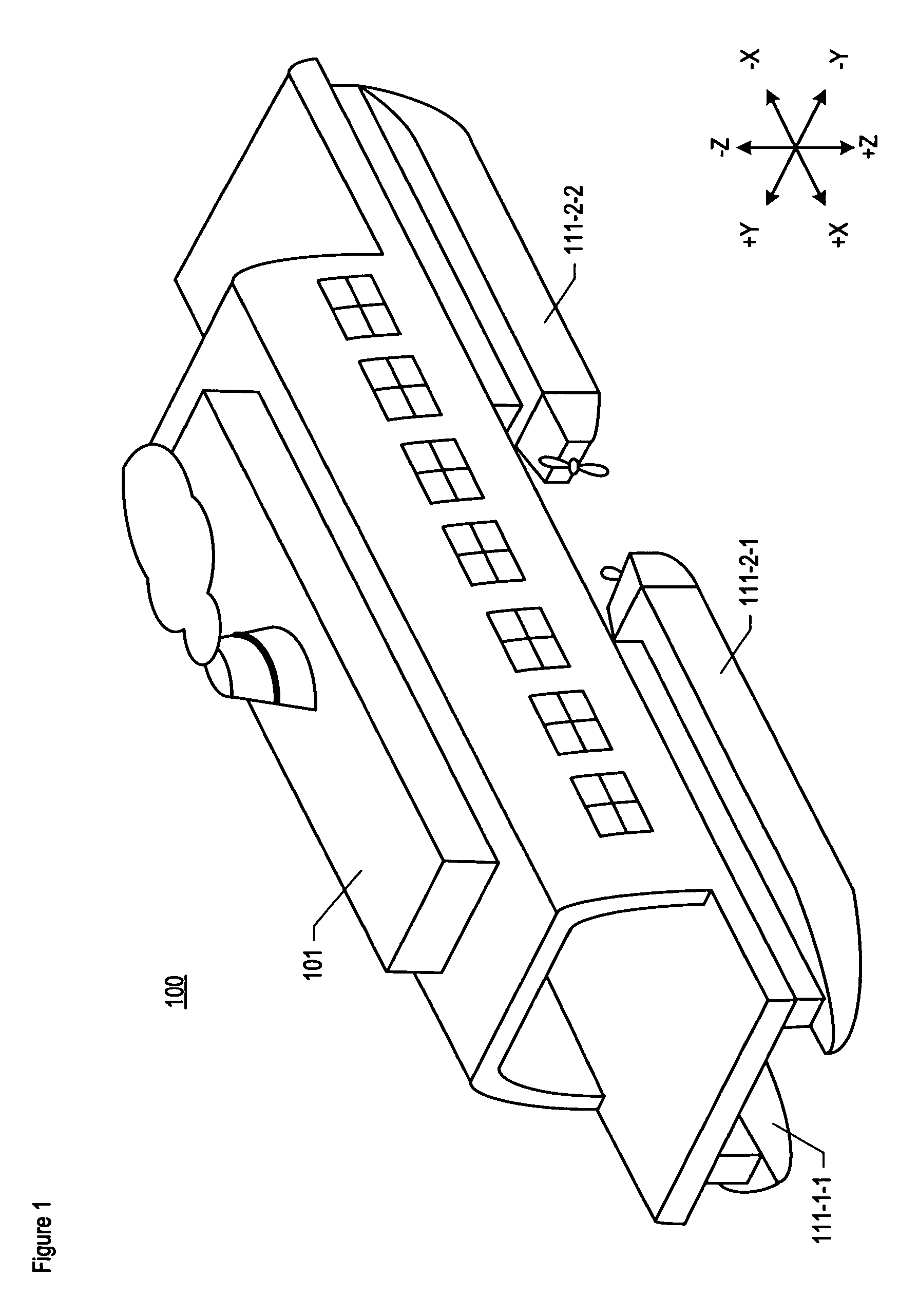
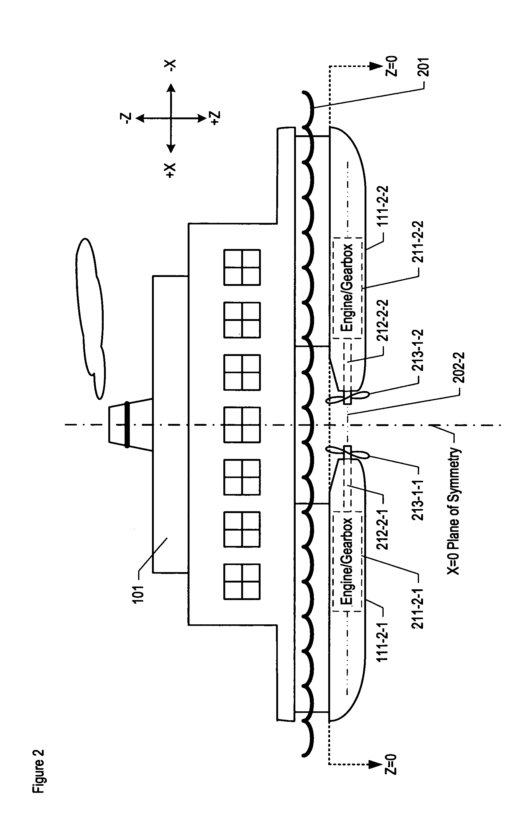
[0016]FIG. 1 depicts an isometric drawing and FIG. 2 depicts a side view drawing of the salient components of the illustrative embodiment of the present invention, ferry 100. FIG. 3 depicts a plan view drawing—taken at elevation Z=0—of ferry 100, as depicted in FIG. 2.

[0017]Ferry 100 comprises:[0018]superstructure 101,[0019]four (4) hulls: hull 111-1-1, hull 111-2-1, hull 111-1-2, and hull 111-2-2;[0020]four (4) engines and gearboxes: engine / gearbox 211-1-1, engine / gearbox 211-2-1, engine / gearbox 211-1-2, and engine / gearbox 211-2-2,[0021]four (4) propeller shafts: propeller shaft 212-1-1, propeller shaft 212-2-1, propeller shaft 212-1-2, and propeller shaft 212-2-2, and[0022]four (4) propellers: propeller 213-1-1, propeller 213-2-1, propeller 213-1-2, and propeller 213-2-2,

interconnected as depicted in FIGS. 1, 2, and 3. Although the illustrative embodiment comprises four sets of hulls / engines / gearboxes / propeller shafts / propellers, it will be clear to those skilled in the art, after...


PUM


Abstract

An efficient double-ended watercraft is disclosed that comprises four low-Froude number hulls: two forward, two aft, two on the port side, and two on the starboard. Each hull comprises an independent engine that drives a propeller shaft and propeller that is located amidships. The propeller shafts on the starboard are collinear, as are the propeller shafts on the port. The propellers on the starboard are near each other and counter rotate, as do the propellers on the port. The propellers are variable-pitch propellers. When the ferry is changes from moving forward to moving in reverse and from reverse to forward, the propellers on the starboard exchange pitch. This enables the ferry to move as efficiently in reverse as it does when forward. The propellers on the port also exchange pitch when changing from moving forward to moving in reverse and from reverse to forward.

Description

FIELD OF THE INVENTION[0001]The present invention relates to naval architecture in general, and, more particularly, to double-ended watercraft.BACKGROUND OF THE INVENTION[0002]Ferries, roll-on / roll-off and other “double-ended” watercraft (i.e., watercraft that often travel in both forward and reverse) require propulsion systems that are efficient for travel in both forward and reverse. In accordance with one technique in the prior art, propulsors (e.g., waterjets, propellers, etc.) on azipods are located at both ends of a double-ended vessel and rotate around a vertical axis so that they point in the desired direction of travel. This technique is disadvantageous, however, because the equipment used to hold and rotate the azipods is heavy, bulky, expensive, and prone to malfunction.[0003]Therefore, the need exists for an improved double-ended watercraft design that avoids this disadvantage.SUMMARY OF THE INVENTION[0004]The present invention is particularly well-suited with double-end...

Claims


Application Information

Patent Timeline
Patent Type & Authority Patents(United States)
IPC IPC(8): B63H5/07
CPCB63B1/107B63B1/12B63H5/08B63H5/10B63B2001/126B63B35/54
Inventor SCHMIDT, TERRENCE W.
Owner LOCKHEED MARTIN CORP
Why Eureka
Try Eureka