Controllable endoscopic sheath apparatus and related method of use

a technology of endoscope and sheath, which is applied in the field of endoscopic devices, can solve the problems of affecting unable to maximize the maneuverability of therapeutic devices at the endoscope tip, and impede the maneuverability of surgical instruments, and achieves the effect of sufficient rigidity

Inactive Publication Date: 2006-07-04
SCI MED LIFE SYST
View PDF28 Cites 1233 Cited by
  • Summary
  • Abstract
  • Description
  • Claims
  • Application Information

AI Technical Summary

Benefits of technology

[0013]In another aspect, the controller device includes a stiffening member disposed alongside the outside of the lumen and adjacent to the endoscope. The lumen further includes a deflectable lumen tip having a naturally deflected state and an elastic memory. The mate

Problems solved by technology

But, this maneuverability is limited by the diameter constraints of the endoscope tip which, in turn, are dictated by the particular body cavity dimensions of the patient.
These designs, however, have failed to maximize the maneuverability of therapeutic devices at the endoscope tip.
Such a limitation impedes the

Method used


Image

  • Controllable endoscopic sheath apparatus and related method of use
  • Controllable endoscopic sheath apparatus and related method of use
  • Controllable endoscopic sheath apparatus and related method of use

Examples


first embodiment

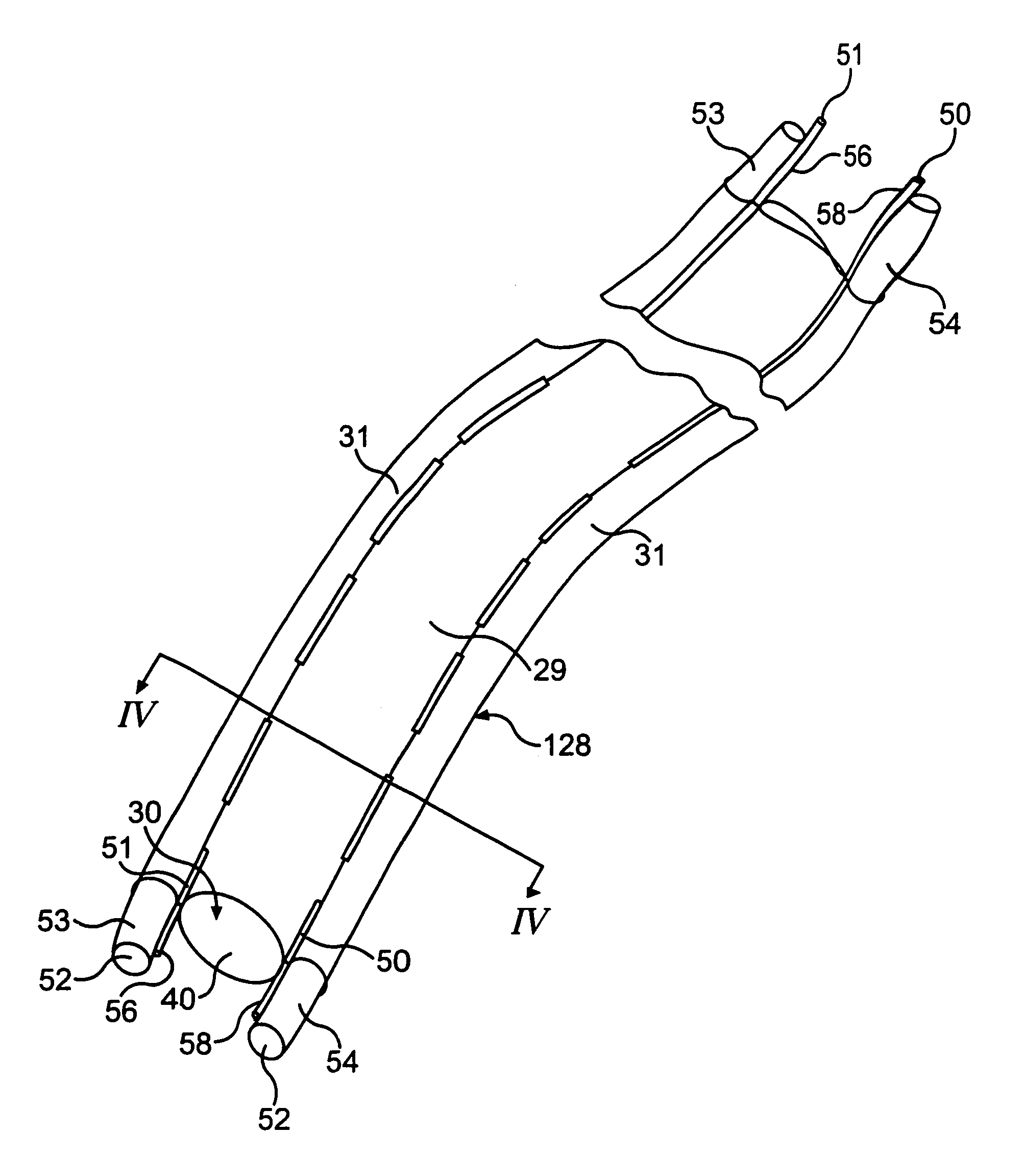
[0058]Accordingly, the amount of lumen deflection can be controlled by limiting the deflection of tip 52 of lumen 53, 54 by extending stiffening member 50, 51 beyond endoscope tip 40. In contrast to the first embodiment, where advancement of wire member 42 enhances the distal end deflection, advancing stiffening member 50, 51 beyond endoscope tip 40 hinders the elastic deflection of tip 52, thus, limiting the deflection of lumen 53, 54.

[0059]Although the drawings depict only one stiffening member per lumen, multiple stiffening members may be used to controllably deflect a particular lumen. Additional stiffening members dispersed along the walls of the lumen offer enhanced control over the direction and deflection of the lumen. For example, by positioning the stiffening members along various points on the perimeter of the lumen, each stiffening member may control a different direction of deflection. The additional stiffening members, as positioned, give the operator the ability to de...

second embodiment

[0061]As an example of this variation of the second embodiment and as shown in FIGS. 6 and 6A. a stiffening member may include sheath guide 60, 61 fixedly disposed to the outside of endoscope 30 and adjacent to lumen 53, 54. As best shown in FIG. 6A, sheath guide 60, 61 is configured to engage with guide pin 64, 65. Guide pin 64, 65 is fixedly disposed along the walls of lumen 53, 54 and adjacent to endoscope 30. Once again, the distal end of sheath guide 60, 61 possesses sufficient rigidity to impede the deflection of the distal end of lumen 53, 54.

[0062]To create the desired distal end deflection, lumen 53, 54 extends beyond endoscope tip 40, as previously described. As the distal end of lumen 53, 54 extends beyond endoscope tip 40, the distal end of guide pin 64, 65 no longer communicates with sheath guide 60, 61. As such, the deflection of tip 52 due to its elastic memory is no longer impeded by sheath guide 60, 61, and the distal end of lumen 53, 54 elastically deflects. Accord...

third embodiment

[0063]In a third preferred embodiment of the present invention, a controllable endoscopic sheath 228 includes an actuator having a flexible extension. The flexible extension eccentrically attaches to a flexible elongated member. This third embodiment of an endoscopic sheath according to the present invention is illustrated in FIGS. 7–12. Preferably, the flexible elongated member includes cable 70, 72, the flexible extension includes spherical mating members 74, 76, 78, and sheath 228 includes an outer sheath 82 and a inner sheath 80. Spherical members 74, 76, 78 are preferably constructed of a stainless steel or plastic material.

[0064]Each cable 70, 72 extends from the proximal end of its corresponding lumen 153, 154 to the distal end, where it eccentrically extends along corresponding spherical mating members 74, 76, 78 positioned at the distal end of lumen 153, 154. As illustrated in FIG. 9, preferably, cable 72 eccentrically extends through each of the spherical mating members 74...


PUM


Abstract

A controllable sheath for optimizing the control of surgical instruments at the operation site includes a flexible sheath surrounding an endoscope and including a lumen extending along the walls of the sheath and adjacent to the endoscope. The lumen permits the passage of surgical instruments from the proximal end of the endoscopic device to the operation site. The lumen extends beyond the distal end of the endoscope and deflects at the distal end as desired by the operator's manipulation of a controller device. This distal end deflection may occur through various different techniques where the ability to deflect the lumen gives the operator increased control and maneuverability over the surgical implements located in the lumen. Depending upon the particular requirements of the surgical procedure, the controllable sheath may include any number of lumens capable of distal end deflection.

Description

[0001]This is a continuation of application Ser. No. 09 / 725,814, filed Nov. 30, 2000, now U.S. Pat. No. 6,761,865, which is a continuation of application Ser. No. 09 / 267,109, filed Mar. 12, 1999, now U.S. Pat. No. 6,179,776 B1, all of which are incorporated herein by reference.BACKGROUND OF THE INVENTION[0002]1. Field of the Invention[0003]The present invention relates to endoscopic devices, and, more particularly, to a sheath, external to an endoscope, that includes working channels capable of controllable deflection at their distal ends, and to a related method of using the sheath during an endoscopic operation.[0004]2. Background of the Related Art[0005]An endoscope is a flexible medical device for insertion into a body passageway or cavity that enables an operator, positioned at a remote external location, to perform certain surgical procedures at a site internal to the patient's body. In general, an endoscope includes a long flexible tubular member equipped with, for example, a...

Claims


Application Information

Patent Timeline
IPC IPC(8): A61B1/00A61B1/018A61B17/221A61B18/14
CPCA61B1/00073A61B1/00135A61B1/00078A61B1/0051A61B1/018
Inventor ADAMS, RONALDBANIK, MICHAELPUGSLEY, CHARLES
Owner SCI MED LIFE SYST
Why Eureka
Try Eureka