Dynamically adjustable stabilization brace

a stabilization brace and dynamic technology, applied in the field of medical devices, can solve the problems of adding to the overall severity of the problem of dealing with bodily injuries, creating the greatest challenges and cost to the medical system, and achieve the effects of stabilizing the spine, improving healing and rehabilitation, and limiting bending, lifting or other activities

Inactive Publication Date: 2006-07-04
AMEI TECH
View PDF69 Cites 21 Cited by
  • Summary
  • Abstract
  • Description
  • Claims
  • Application Information

AI Technical Summary

Benefits of technology

[0008]Certain embodiments of the present invention may provide one or more technical advantages. Certain embodiments of the invention may provide all, some, or none of these advantages. For example, certain embodiments provide a stabilization brace that allows a range of motion of the user's spine or other joint, while limiting the degree of flexion to a predetermined range, to improve healing and rehabilitation relative to techniques in which the spine or other joint is substantially immobilized using a brace or otherwise. Certain embodiments may provide resistance against such flexion to stabilize the spine or other joint and limit bending, lifting, or other activities. In certain embodiments, the predetermined range of flexion, the resistance provided against such flexion, or both, may be adjusted according to particular needs. Such adjustability may improve the effectiveness of rehabilitation and ultimately help to wean the user off of the stabilization brace. In certain embodiments, the stabilization brace may also provide belts with canting mechanisms that allow the stabilization brace to be properly fitted for each particular user. Such can

Problems solved by technology

The relative ease with which injuries to the back and other portions of the body are incurred merely adds to the overall severity of the problem

Method used


Image

  • Dynamically adjustable stabilization brace
  • Dynamically adjustable stabilization brace
  • Dynamically adjustable stabilization brace

Examples


Embodiment Construction

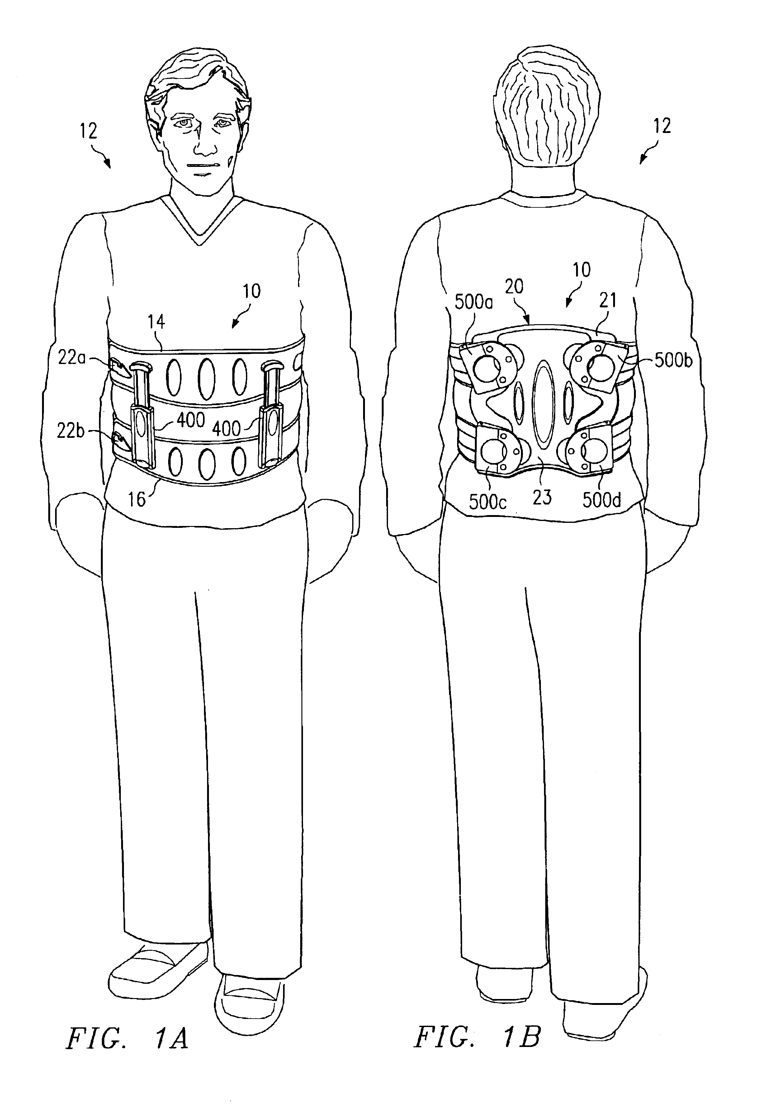
[0018]FIGS. 1A and 1B are front and rear views, respectively, illustrating a user 12 wearing an example stabilization brace 10. In the illustrated embodiment, stabilization brace 10 is operable to control the range of motion of the user's spine, limiting the degree of flexion to a predetermined range. However, in other embodiments, stabilization brace 10 may be modified to control the range of motion and limit the degree of flexion of any joint, such as the knee, elbow, or neck.

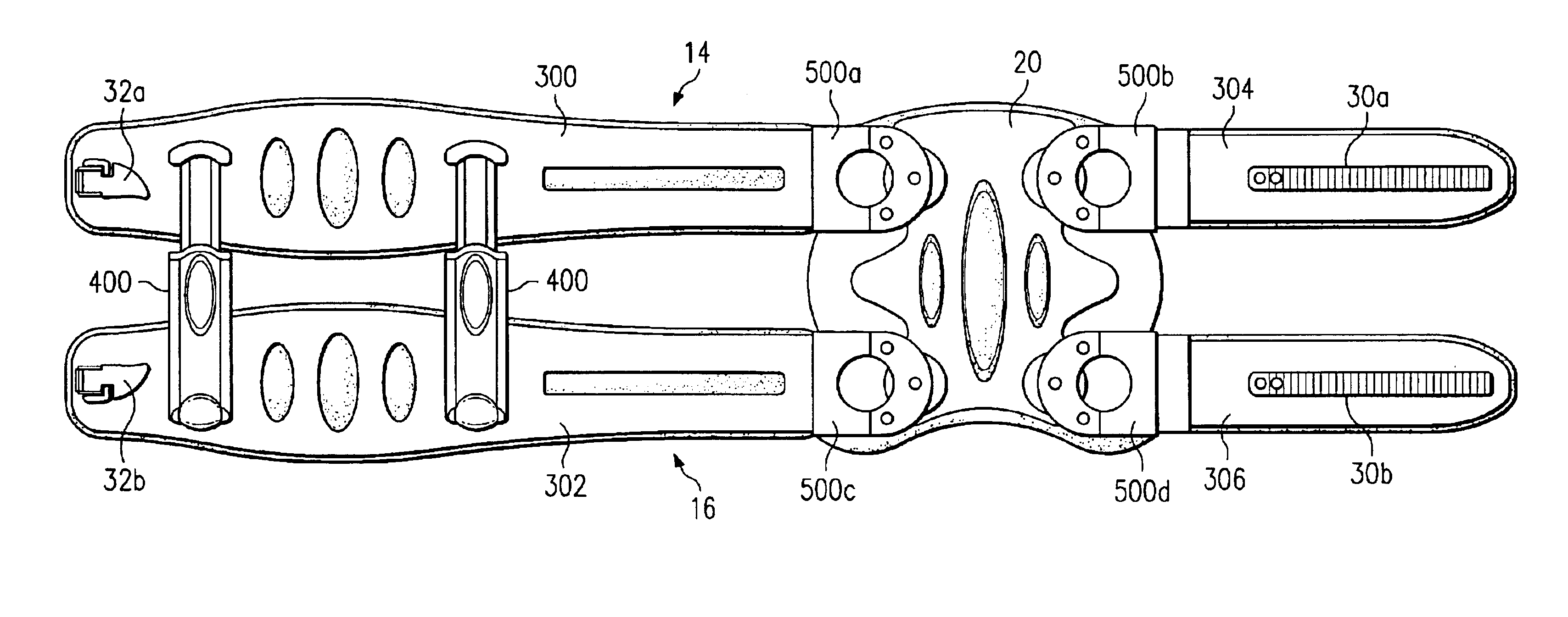
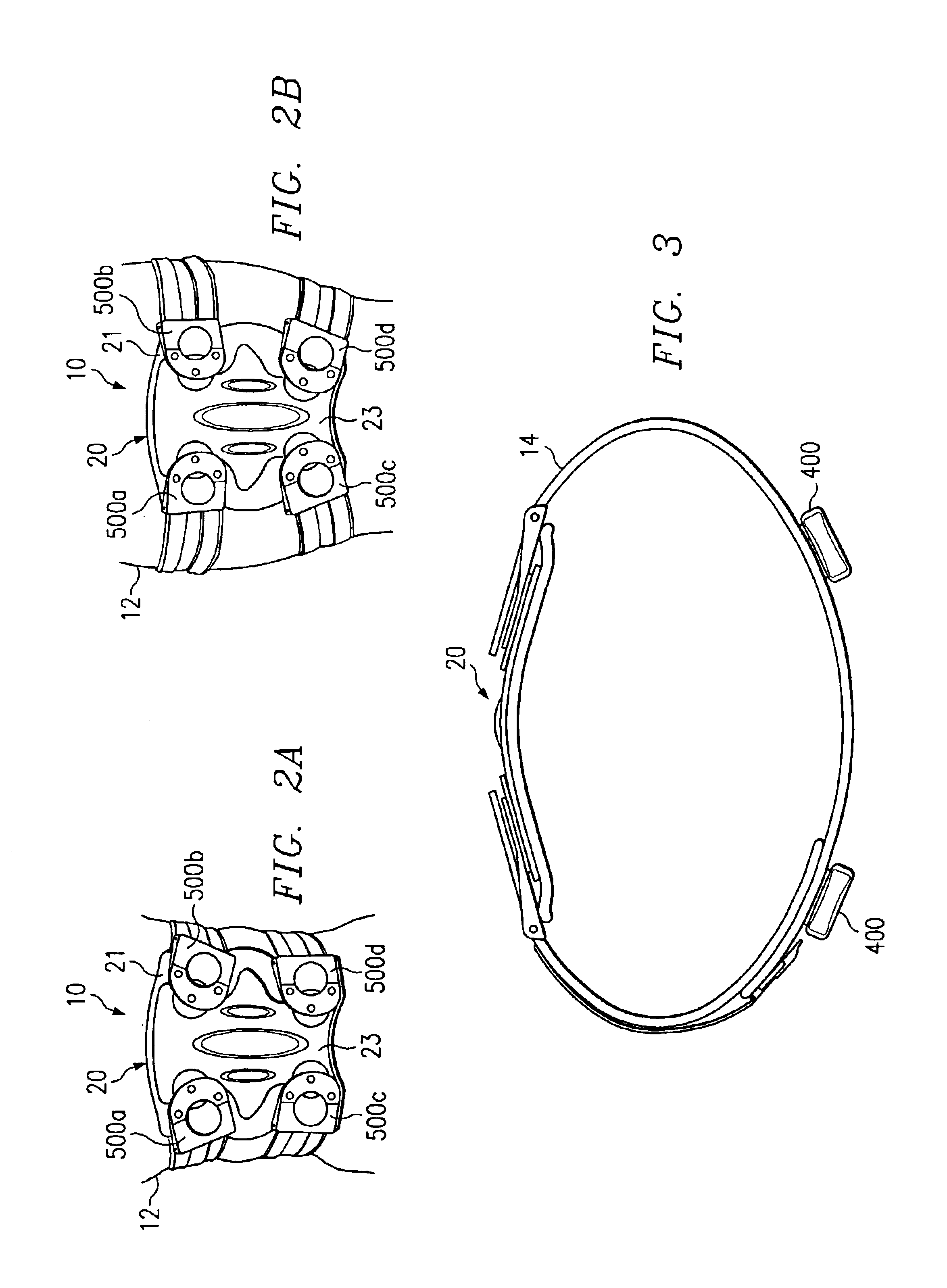
[0019]Stabilization brace 10 includes an upper belt 14 and a lower belt 16. Belts 14, 16 may be formed in any suitable manner that allows them to be positioned around a desired portion of the user's body. Example details of one embodiment of belts 14, 16 are described in greater detail below with reference to FIG. 4. In the illustrated embodiment, stabilization brace 10 also includes one or more supports 400, a backplate 20, a pair of canting mechanisms 500 associated with each support belt 14, 16, and a pair...


PUM


Abstract

In one embodiment, a stabilization brace includes an upper belt configured to be positioned around a portion of a user's body, a lower belt configured to be positioned around the portion of the user's body, and one or more supports coupled between the upper and lower belts. Each support includes a housing, a piston slidably engaged with the housing, and a motion limiter adjustably coupled to the housing in one of a plurality of predetermined positions, the support operable to limit flexion of the portion of the user's body to a predetermined range according to the position of the motion limiter.

Description

RELATED APPLICATIONS[0001]This application claims the benefit under 35 U.S.C. §119(e) of U.S. Provisional Application Ser. No. 60 / 419,809 filed Oct. 17, 2002 entitled “Dynamically Adjustable Stabilization Brace.”TECHNICAL FIELD OF THE INVENTION[0002]This invention relates to the field of medical devices and, more particularly, to a dynamically adjustable stabilization brace.BACKGROUND OF THE INVENTION[0003]People have long dealt with the pain, aggravation, and loss of productivity arising from bodily injuries, such as those to the back, knees, and elbows. In fact most people will at some point in their lives be at least temporarily incapacitated by back pain, particularly low back pain. The relative ease with which injuries to the back and other portions of the body are incurred merely adds to the overall severity of the problem of dealing with bodily injuries. The forms of treatment vary over the length of time that a patient experiences pain. For example, eighty percent of low bac...

Claims


Application Information

Patent Timeline
IPC IPC(8): A61F5/00A61F5/02
CPCA61F5/024
Inventor REINECKE, STEVEN M.THOMPSON, RICHARD A.
Owner AMEI TECH
Why Eureka
Try Eureka