Electric motor control apparatus

a technology of electric motors and control apparatuses, applied in the direction of dynamo-electric converter control, multiple dynamo-motor starters, transportation and packaging, etc., can solve the problems of increasing power loss, and achieve the effect of reducing the total amount of power loss

Active Publication Date: 2006-07-04
HONDA MOTOR CO LTD
View PDF10 Cites 10 Cited by
  • Summary
  • Abstract
  • Description
  • Claims
  • Application Information

AI Technical Summary

Benefits of technology

[0009]Therefore, it is an object of the present invention to provide an electric motor control apparatus having at least two electric motors acting as a generator and a motor and suppressing power loss caused by driving the electric motor acting as a motor with a generated output of the electric motor acting as a generator, resolving the above problem.

Problems solved by technology

When the PWM control is performed for both of the first inverter 105 and the second inverter 106 in this manner, however, there has been a problem of increasing power loss accompanied by the ON-OFF control action of the switching element in each of the inverters.

Method used


Image

  • Electric motor control apparatus
  • Electric motor control apparatus
  • Electric motor control apparatus

Examples


first embodiment

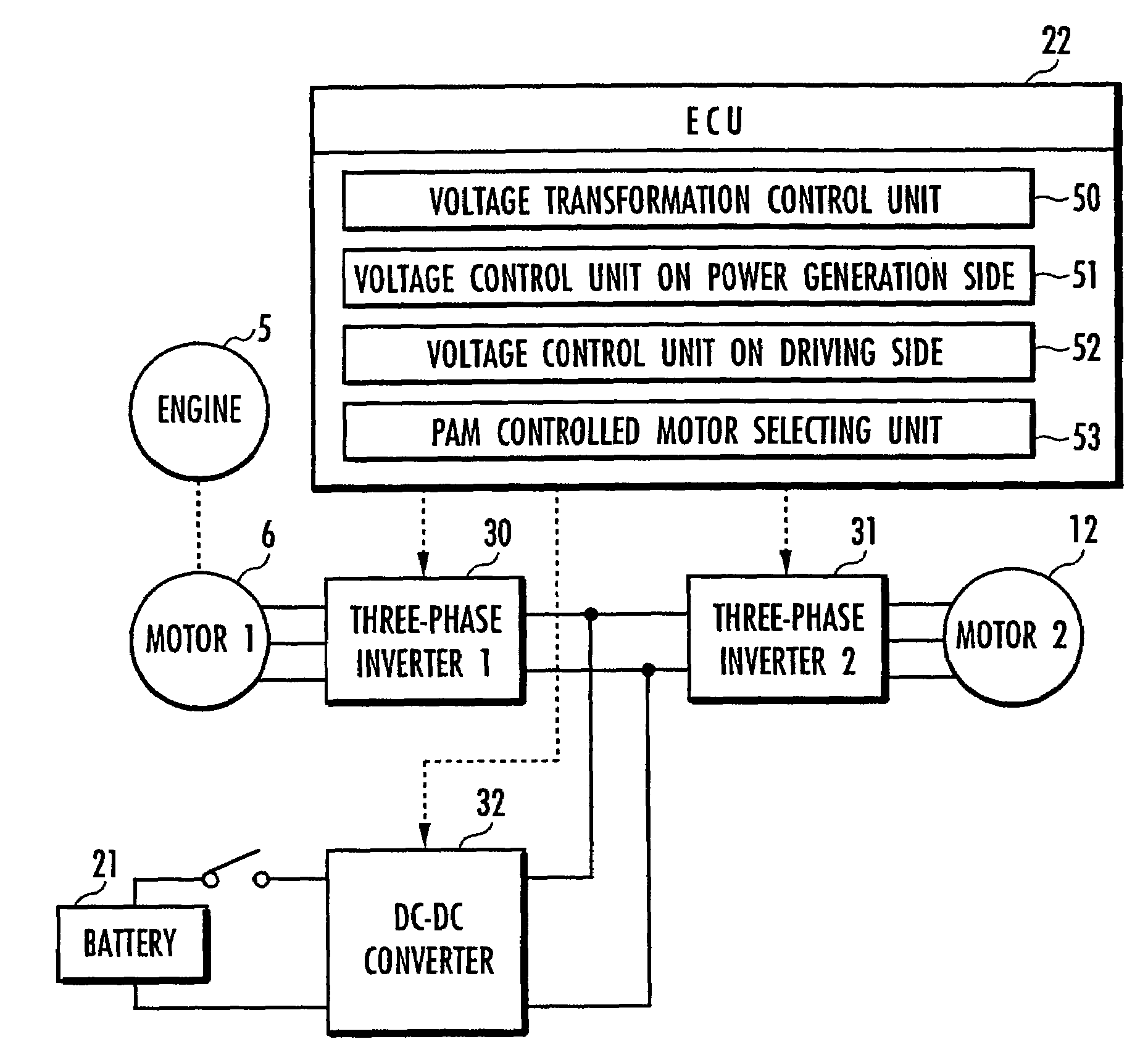
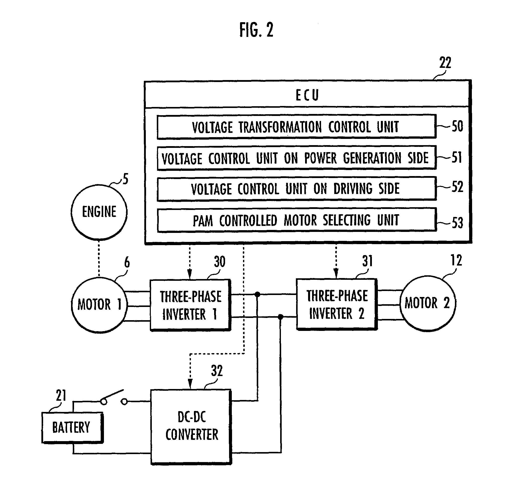
[0048]Referring to FIG. 2, the electric motor control apparatus according to the first embodiment comprises the first electric motor 6, the second electric motor 12, a first inverter 30, a second inverter 31, the battery 21, a DC—DC converter 32, and an ECU 22 in the first embodiment. The battery 21 is then connected to the first inverter 30 and the second inverter 31 via the DC—DC converter 32 and control signals output from the ECU 22 control the operations of the first inverter 30, the second inverter 31, and the DC—DC converter 32.

[0049]When the electric motor 6 acts as a motor, the first inverter 30 generates a three-phase drive voltage from a DC voltage input from the DC—DC converter 32 or the second inverter 31 and outputs the drive voltage to the first electric motor 6. When the first electric motor 6 acts as a generator, the first inverter 30 converts a three-phase generated voltage input from the first electric motor 6 to a DC voltage and outputs the DC voltage to the DC—D...

second embodiment

[0086]Referring to FIG. 8, an electric motor control apparatus according to the present invention comprises a first electric motor 6, a second electric motor 12, a first inverter 30, a second inverter 31, and an ECU 22 in a second embodiment. Then, the first inverter 30 is connected to the second inverter 31 and control signals output from the ECU 22 control the operations of the first inverter 30 and the second inverter 31. The same reference characters have been used as in FIG. 3 for the same parts as in the control block diagram in the first embodiment shown in FIG. 3 and their description is omitted here.

[0087]When the first electric motor 6 is operated as a generator and the second electric motor 12 is operated as a motor, the voltage control unit on the power generation side 60 in the second embodiment executes “control pattern 1” for transforming a generated voltage of the first electric motor 6 with the PWM control by using the first inverter 30 and thereby changing a drive ...


PUM


Abstract

An electric motor control apparatus suppressing power loss caused by driving an electric motor acting as a motor with a generated output of an electric motor acting as a generator. The electric motor control apparatus comprises a PAM controlled motor selecting unit (53) for determining which of “control pattern 1” and “control pattern 2” should be executed by comparison in total power loss, where a voltage control unit on the power generation side (51) performs voltage transformation with a PWM control in a first inverter (30) and generates a drive voltage for a second electric motor (12) with a PAM control in a second inverter (31) in the control pattern 1 and a voltage control unit on the driving side (52) outputs a rectified voltage from a generated voltage of a first electric motor (6) without voltage transformation in the first inverter (30) and generates a drive voltage for the second electric motor (12) with a PWM control in the second inverter (31) in the control pattern 2.

Description

BACKGROUND OF THE INVENTION[0001]1. Field of the Invention[0002]The present invention relates to an electric motor control apparatus having at least two electric motors acting as a generator and a motor and causing them to operate in cooperation with each other.[0003]2. Related Background Art[0004]There is an already known method of controlling an output of an electric motor, a so-called PWM control for varying the amount of electricity supplied to the electric motor by means of an ON-OFF control action of a switching element provided in an inverter (for example, refer to Japanese Patent No. 3244845).[0005]Referring to FIG. 13, there is shown an example of a system for controlling an output of an electric motor by means of the PWM control, showing a configuration diagram of a hybrid vehicle having an engine 100, a first electric motor 101 and a second electric motor 102 as driving sources. In this type of hybrid vehicle, the first electric motor 101 and the second electric motor 102...

Claims


Application Information

Patent Timeline
Patent Type & Authority Patents(United States)
IPC IPC(8): H02P5/00B60L9/18H02P5/74
CPCB60L15/08Y02T10/64
Inventor OCHIAI, SHINOBUURUSHIHARA, KEISUKE
Owner HONDA MOTOR CO LTD
Why Eureka
Try Eureka