Slewing type working machine

a working machine and slewing technology, applied in the direction of fluid couplings, servomotors, couplings, etc., can solve the problems of increasing load, significant power loss, increasing power loss, etc., and achieve the effect of reducing back pressur

Inactive Publication Date: 2014-11-11
KOBELCO CONSTR MASCH CO LTD
View PDF14 Cites 10 Cited by
  • Summary
  • Abstract
  • Description
  • Claims
  • Application Information

AI Technical Summary

Benefits of technology

[0013]An object of the present invention is to provide a slewing-type working machine capable of reducing back pressure generated when slewing is performed to thus suppress power loss due to the back pressure. The slewing-type working machine provided by the present invention includes: a base carrier; an upper slewing body mounted on the base carrier so as to be capable of slewing; a hydraulic motor including first and second ports and adapted to receive supply of hydraulic fluid from one of the ports and discharge the hydraulic fluid from the other one of the ports, thereby operating to slew the upper slewing body; a hydraulic pump discharging the hydraulic fluid which is to be supplied to the hydraulic motor; a slewing operation device including an operating member to which an operation is applied to input a command for the slewing and outputting an operation signal corresponding to an operation applied to the operating member; a control valve which is operated so as to control supply of hydraulic fluid to the hydraulic motor and discharge of hydraulic fluid from the hydraulic motor, based on the operation signal of the slewing operation device; a first pipe-line connecting the first port of the hydraulic motor to the control valve; a second pipe-line connecting the second port of the hydraulic motor to the control valve; a communication switching device provided between both of first and second pipe-lines and a tank to be switched among a state of cutting off both of the first and second pipe-lines from the tank, a state of bringing the first pipe-line into communication with the tank while cutting off the second pipe-line from the tank, and a state of bringing the second pipe-line into communication with the tank while cutting off the first pipe-line from the tank; and a switching command section which inputs a command signal to the communication switching device to switch the states thereof, the switching command section adapted to cause the communication switching device to bring, when the upper slewing body is slewed by the hydraulic motor, only a pipe-line that is one of the first and second pipe-lines and corresponds to a pipe-line on the discharge side of the hydraulic motor into communication with the tank, while bypassing the control valve.

Problems solved by technology

This technique, however, involves a problem of generating back pressure during slewing to increase power loss.
The back pressure increases a motor flow-in-side, i.e., a meter-in-side, pressure, in other words, that is, a discharge pressure of the hydraulic pump 10, to thus increase load on the hydraulic pump 10, resulting in significant power loss.

Method used


Image

  • Slewing type working machine
  • Slewing type working machine
  • Slewing type working machine

Examples


first embodiment

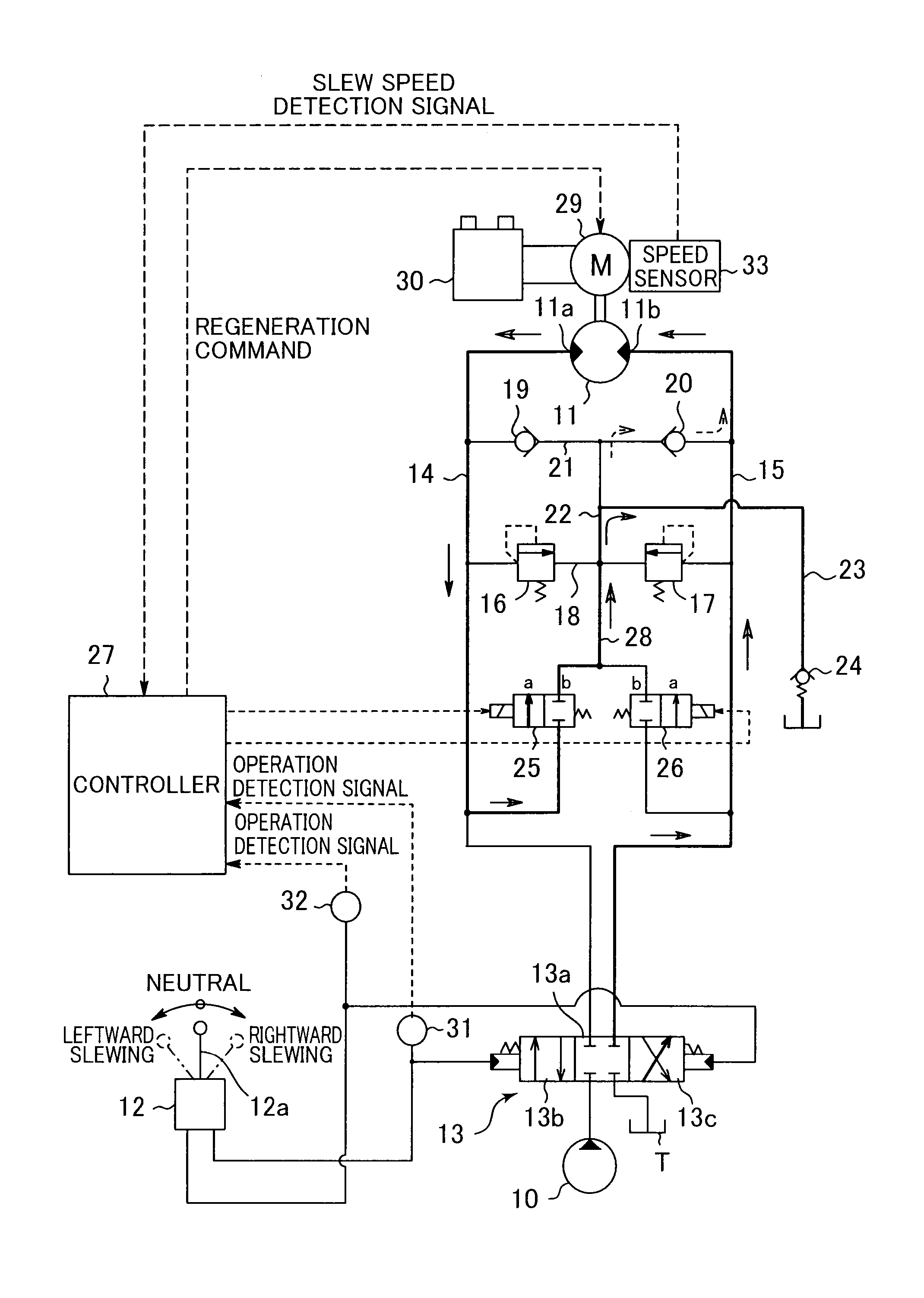
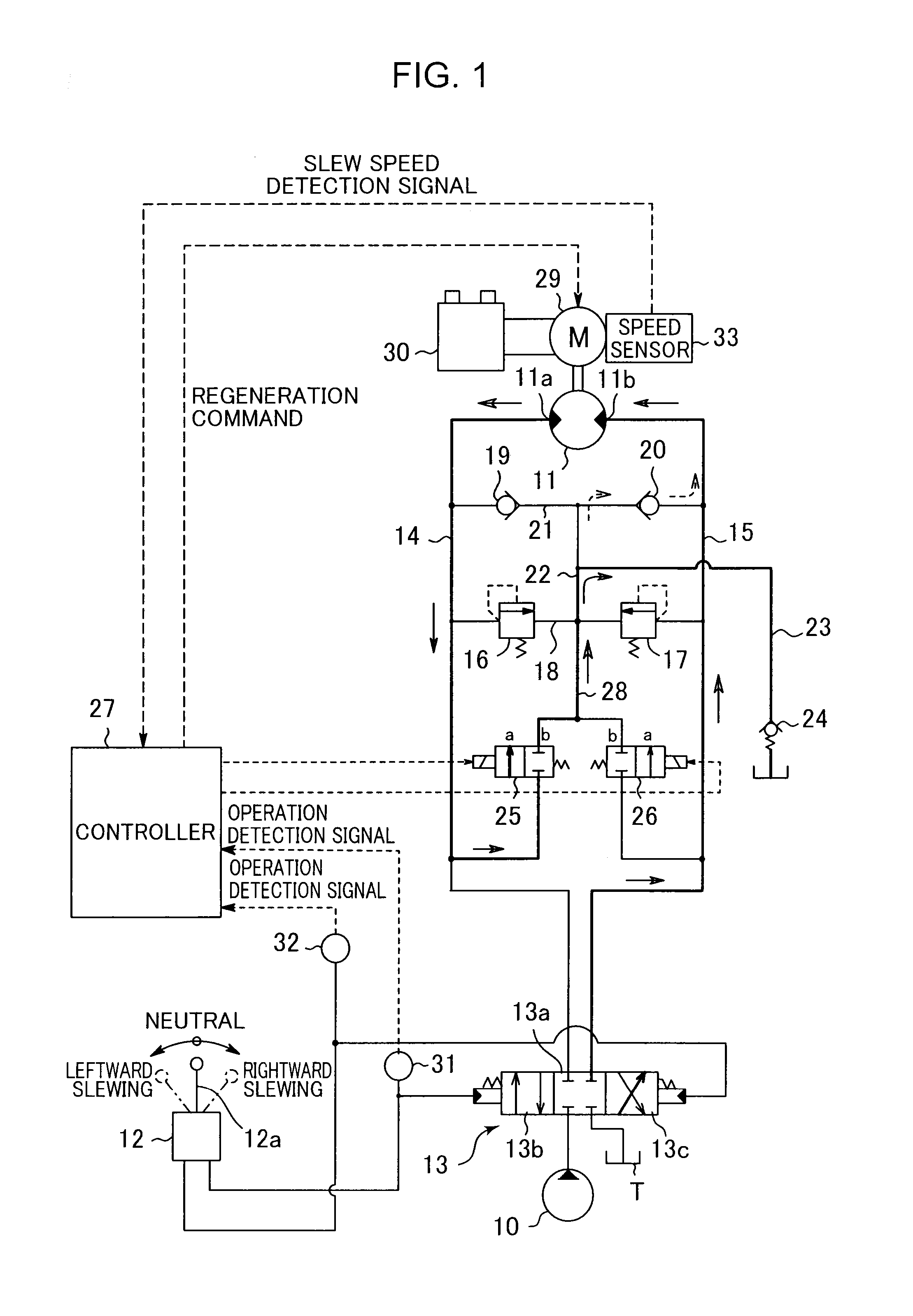
[0023]FIG. 1 shows a hydraulic circuit according to the present invention. The circuit includes: a hydraulic pump 10 as a hydraulic pressure source, which is driven by an engine not graphically shown; a slewing hydraulic motor 11 which is rotated by supply of hydraulic fluid discharged from the hydraulic pump 10 to drive the upper slewing body 2 to slew it, a remote-control valve 12 as a slewing operation device including a lever 12a to which an operation is applied to input a slewing command; and a control valve 13 which is a pilot controlled selector valve that can be operated by the remote-control valve 12 and is provided between the hydraulic motor 11 and a pair of the hydraulic pump 10 and a tank T.

[0024]The hydraulic motor 11 includes a left port 11a and a right port 11b which are first and second ports, respectively. When supplied with hydraulic fluid through the left port 11a, the hydraulic motor 11 discharges the hydraulic fluid through the right port 11b while leftward sle...

second embodiment

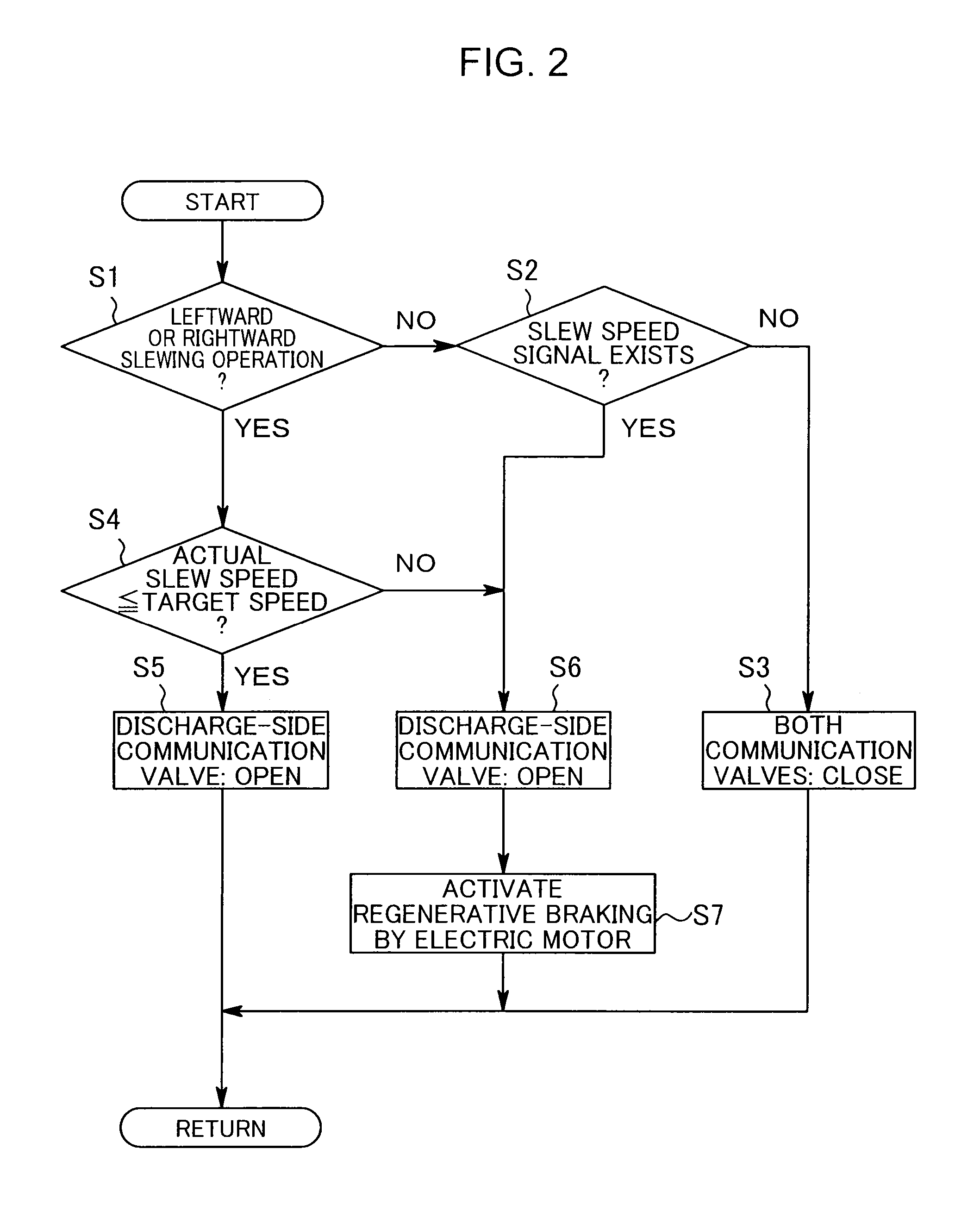
[0044]FIG. 4 shows a specific control operation by the controller 27 according to the

[0045]The controller 27 judges in step S11 whether or not rightward or leftward slewing operation has been performed; if NO, i.e., if no operation, the controller 27, assuming that the slewing is being decelerated or stopped by a neutral return operation, causes both communication valves 25 and 26 to be closed in step S12. In contrast, in the case of YES in step S11, i.e., in the case where any operation has been performed, the controller 27, assuming that the slewing is being accelerated, steadily performed, or decelerated by a neutral return operation, compares an actual slew speed with a target speed in step S 13. In the case of YES in step S13, i.e., in the case of the actual slew speed being equal to or lower than the target speed, the controller 27, assuming that the slewing is being steadily performed or accelerated, causes the opposite-side communication valve to be opened in step S14 and re...


PUM


Abstract

A slewing-type working machine capable of reducing back pressure generated during slewing. The slewing-type working machine includes: a base carrier; an upper slewing body; a hydraulic motor including first and second ports and slewing the upper slewing body; a hydraulic pump, a slewing operation device including an operating member; a control valve controlling the hydraulic motor based on the operation signal of the slewing operation device; first and second pipe-lines connecting the first and second ports of the hydraulic motor to the control valve; a communication switching device capable of switching communication and cutting of between both pipe-lines and the tank; and a switching command section operating the communication switching devices, when the upper slewing body is slewed, to bring only a pipe-line, which corresponds to a discharge-side pipe-line of the hydraulic motor, of the pipe-lines into communication with the tank, while bypassing the control valve.

Description

TECHNICAL FIELD[0001]The present invention relates to a slewing-type working machine such as an excavator.BACKGROUND ART[0002]The background art of the present invention will be described using an excavator as an example.[0003]For example, as shown in FIG. 7, a general excavator comprises a crawler-type base carrier 1, an upper slewing body 2 mounted on the base carrier 1 so as to be capable of being slewed around an axis X perpendicular to the ground, and an excavating attachment 3 attached to the upper slewing body 2. The excavating attachment 3 includes: a boom 4 capable of being raised and lowered; an arm 5 attached to a tip of the boom 4; a bucket 6 attached to a tip of the arm 5; and respective cylinders (hydraulic cylinders) for actuating the boom 4, the arm 5, and the bucket 6, namely, a boom cylinder 7, an arm cylinder 8, and a bucket cylinder 9.[0004]FIG. 8 shows an example of a conventional hydraulic circuit for slewing the upper slewing body 2. The circuit includes: a hy...

Claims


Application Information

Patent Timeline
Patent Type & Authority Patents(United States)
IPC IPC(8): E02F9/12E02F9/22F15B21/14
CPCF15B2211/6313F15B2211/6336E02F9/2228F15B13/024F15B2211/50527F15B21/14F15B2211/3116F15B2211/6316F15B9/14F15B21/082F15B2211/7058F15B2211/88E02F9/2285E02F9/123F15B11/024F15B21/087F15B2011/0243
Inventor KAMIMURA, YUSUKE
Owner KOBELCO CONSTR MASCH CO LTD
Why Eureka
Try Eureka