Optical module and camera module

a technology of optical modules and lens barrels, applied in the field of optical modules, can solve the problems of large power loss, inconvenient movement of optical parts such as lens barrels, and disadvantages of thin construction of lens drivers, and achieve the effect of suppressing power loss and ensuring the accuracy of movement of optical parts

Inactive Publication Date: 2005-09-22
SEIKO INSTR INC
View PDF1 Cites 13 Cited by
  • Summary
  • Abstract
  • Description
  • Claims
  • Application Information

AI Technical Summary

Benefits of technology

[0034] According to the present invention, it is possible to provide an optical module that is thin, allows freedom of design in configuration, and assures the accuracy of movement of an optical part while suppressing power loss.

Problems solved by technology

Since the technique as disclosed in JP 3-294809 A adopts a vertical mounting arrangement for the tubular stepping motor, the length of the motor body constituting the tubular shape of the stepping motor takes up a large proportion in the thickness direction of the lens driver serving as an optical module, making the technique disadvantageous for realizing a thin construction of the lens driver.
However, the worm gear, which effects power transmission by obtaining a large reduction ratio with one gear stage while permitting a slip between the worm 9 and the worm wheel 11, involves a large power loss, making it necessary for the stepping motor 8 used to generate a large torque.
Further, the movement of an optical part such as a lens barrel requires precision.
However, this construction of the tubular stepping motor cannot alter the basic requirement that the rotor be arranged inside the tubular stator, and thus allows no degree of freedom in terms of the stepping motor configuration.
Hence, there is also no degree of freedom in designing the configuration of the lens driver equipped with the tubular stepping motor, making this lens driver (optical module) not suitable for applications where its configuration is to be changed in conformity with the confined installation space within the thin electronic apparatus in which it is to be installed.

Method used


Image

  • Optical module and camera module
  • Optical module and camera module
  • Optical module and camera module

Examples


first embodiment

[0052] the present invention is described with reference to FIGS. 1 through 4.

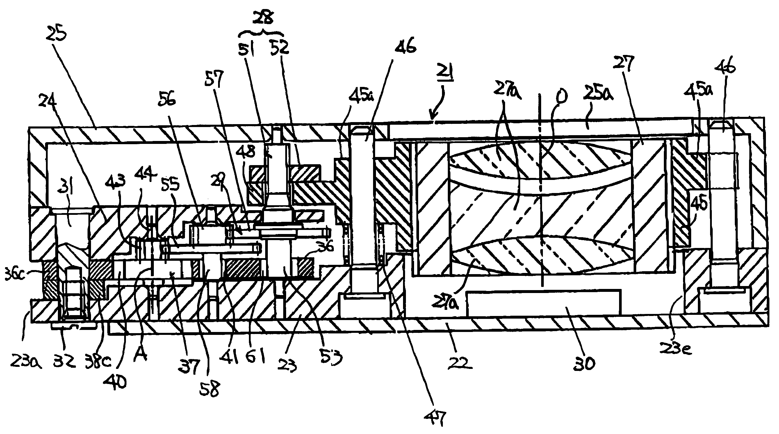
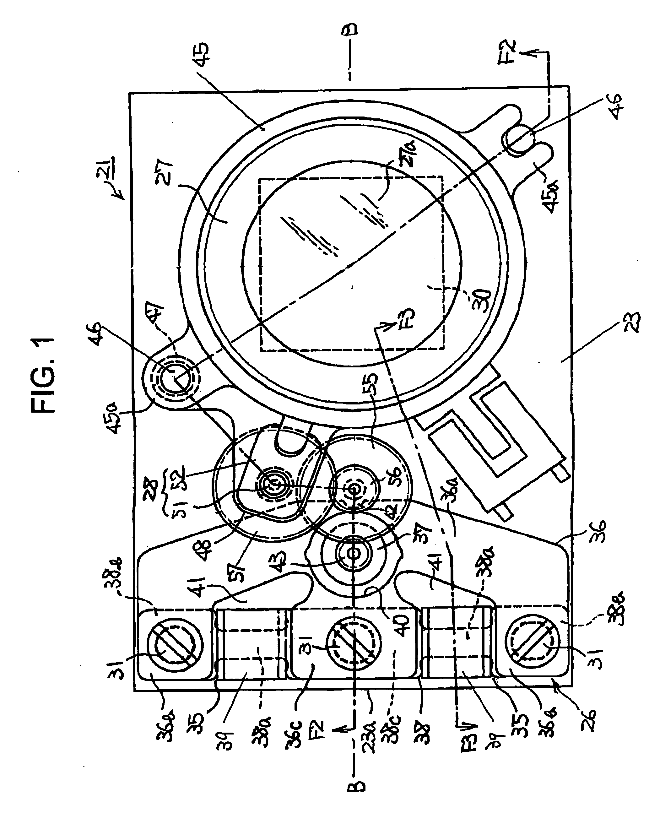
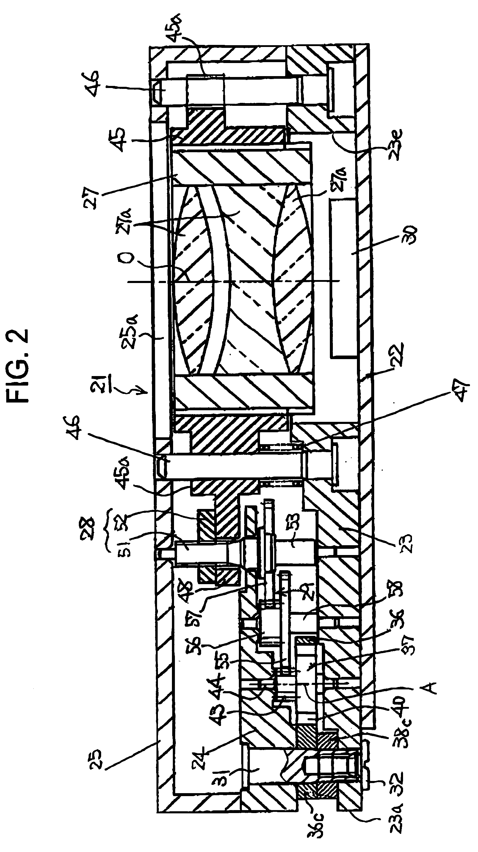
[0053] Referring to FIGS. 1 and 2, denoted by reference numeral 21 is an optical module, for example, a lens driver, which is mounted to a thin electronic apparatus such as a card-type digital camera or a camera-equipped portable telephone. The lens driver 21 includes a circuit board 22, a base plate 23, a gear support 24, a cover 25, a stepping motor 26, an optical part such as a lens barrel 27, moving means 28, and a reduction gear train 29 serving as a gear train.

[0054] The circuit board 22 is a hard board with an image pickup element 30 such as a CCD or a CMOS mounted on one surface thereof. A base plate 23 is fitted onto the one surface of the circuit board 22. The base plate 23 is, for example, rectangular in shape, and has in its one longitudinal end portion a hole 23e receiving the image pickup element 30 and allowing the placement of the lens barrel 27. The gear support 24 is arranged so as to be...

third embodiment

[0081] the stepping motor 26 includes a pair of the coil blocks 35. Each of the coil blocks 35 includes the iron core 38 having the yoke connecting portions 38b and 38c integrally provided to the opposite longitudinal ends of the core portion 38a, and the excitation coil 39 wound around the core portion 38a. The coil blocks 35 are arranged along the edge 23b constituting the long side of the rectangular base plate 23.

[0082] The yoke 36 has, in addition to the magnetic path portion 36a, a pair of the end portions 36b and a pair of the end portions 36c. The pair of end portions 36b are each connected to the yoke connecting portion 38b of each of the two coil blocks 35, and the pair of the other end portions 36c are each connected to the other yoke connecting portion 38c of each of the two coil blocks 35. The section of the magnetic path portion 36a which connects the pair of end portions 36c with each other at the shortest distance is arranged along the edge 23a constituting the shor...

fourth embodiment

[0086] the base plate 23 has an octagonal shape with diagonal edges 23c and 23d. The stepping motor 26 includes a pair of the coil blocks 35. Each of the coil blocks 35 includes the iron core 38 having the yoke connecting portions 38b and 38c integrally provided at the opposite longitudinal ends of the core portion 38a, and the excitation coil 39 wound around the core portion 38a. The two coil blocks 35 are each arranged along the diagonal edge 23c of the base plate 23.

[0087] The magnetic path portion 36a of the yoke 36 has a pair of the end portions 36b and a pair of the end portions 36c. The pair of end portions 36b are each connected to the yoke connecting portion 38b of each of the two coil blocks 35, and the pair of the other end portions 36c are each connected to the other yoke connecting portion 38c of each of the two coil blocks 35. The section of the magnetic path portion 36a which connects the pair of end portions 36c with each other at the shortest distance is arranged a...


PUM


Abstract

Provided is an optical module that is thin, allows freedom of design in configuration, and assures the accuracy of movement of an optical part while suppressing power loss. A stepping motor 26 and a lens barrel 27 that is moved by moving means 28 are positioned offset from each other along a base plate 23, and the optical axis of the lens barrel 27 and the axis of a rotor 37 provided in the stepping motor 26 are arranged in parallel with each other on one surface of the base plate 23. Further, a reduction gear train 29, which operatively couples the rotor 37 and the moving means 28 together, is arranged on the one surface. The stepping motor 26 consists of a flat-shaped motor equipped with: coil blocks 35 each having an excitation coil 39 horizontally mounted along the base plate 23; a yoke 36 whose magnetic path portion 36a excluding end portions 36b and 36c connected with the coil blocks 35 is provided so as not to overlap the coil blocks 35; and the rotor 37 arranged within a rotor pass-through hole 40 of the yoke 36.

Description

BACKGROUND OF THE INVENTION [0001] 1. Field of the Invention [0002] The present invention relates to an optical module equipped with an optical part that is moved for focus adjustment, zooming, and the like, and more particularly to an optical module and a camera module suitable for being mounted on thin electronic apparatuses such as a card-type digital camera or a camera-equipped portable telephone. [0003] 2. Description of the Related Art [0004] Conventionally, there is known a lens driver (optical module) in which, in order to move a lens barrel holding a lens to effect focus adjustment, the drive shaft of a tubular stepping motor is formed by a feed screw, and a rack member protruding from a lens barrel holder holding the lens barrel is brought into mesh with the feed screw, with the lens barrel being moved along an optical axis thereof through the intermediation of the rack member as the stepping motor rotates in forward and reverse directions, thereby effecting a focusing ope...

Claims


Application Information

Patent Timeline
Patent Type & Authority Applications(United States)
IPC IPC(8): G02B7/02G02B7/04G02B7/08G02B7/10G02B15/14G03B3/10G03B13/32H02K37/16
CPCG02B7/08H02K37/16G02B7/102
Inventor SATODATE, TAKAYUKIHASEGAWA, HARUHIKOSUZUKI, MAKOTOKUME, AKIRA
Owner SEIKO INSTR INC
Why Eureka
Try Eureka