Voltage regulator

a voltage regulator and voltage field technology, applied in the direction of electric variable regulation, process and machine control, instruments, etc., can solve the problems of deterioration of the starting characteristics of the voltage regulator, difficult to sufficiently reduce the limit current, and difficult to adjust the transistor b>7/b> and the resistor, so as to enhance the accuracy of the limit current value and the short-circuit current value, suppress heat generation more effectively, and suppress electric power loss

Inactive Publication Date: 2011-08-23
ABLIC INC
View PDF3 Cites 10 Cited by
  • Summary
  • Abstract
  • Description
  • Claims
  • Application Information

AI Technical Summary

Benefits of technology

[0012]The present invention has been made to solve the above-mentioned problems, and therefore an object thereof is to provide a voltage regulator including an overcurrent protection circuit in which accuracy of a limit current value and a short-circuit current value is enhanced.
[0018]According to the voltage regulator including the overcurrent protection circuit of the present invention, the overcurrent protection circuit is formed so that the output current is controlled by the second error amplifier circuit which amplifies the difference between the voltage set by the second reference voltage and the voltage based on the output voltage, and the voltage of the voltage generation circuit and outputs the amplified difference. Accordingly, it is possible to provide the voltage regulator including the overcurrent protection circuit, which is capable of enhancing accuracy of the limit current value and the short-circuit current value irrespective of a process variation in manufacturing, and suppressing electric power loss when the overcurrent flows through the output transistor.
[0019]Further, the second reference voltage is supplied from the temperature detection circuit in which the output voltage thereof changes in accordance with the temperature, and hence the limit current value and the short-circuit current value can be controlled in accordance with temperature, which enables to suppress heat generation more effectively.

Problems solved by technology

However, it is difficult to adjust the transistor 7 and the resistor 6 with accuracy when they are manufactured.
For this reason, there occurs a problem that, when the limit current is set to be small, variations in short-circuit current causes deterioration of starting characteristics of the voltage regulator because of a relationship between the output current and the output voltage.
In other words, it is difficult to sufficiently reduce the limit current for securing the starting characteristics of the voltage regulator.
However, in the conventional overcurrent protection circuit 50, it is impossible to control the limit current value and the short-circuit current value by the internal temperature of the voltage regulator.

Method used


Image

  • Voltage regulator
  • Voltage regulator
  • Voltage regulator

Examples


first embodiment

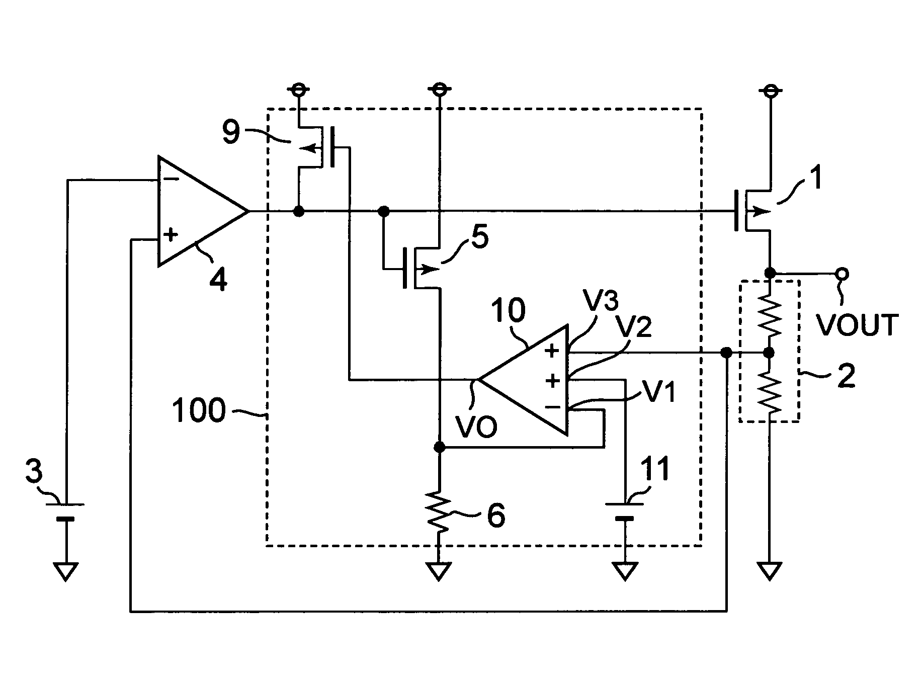
[0027]FIG. 1 is a circuit diagram of a voltage regulator according to the present invention.

[0028]The voltage regulator according to the first embodiment includes an output transistor 1 which is a PMOS transistor, an output voltage divider circuit 2, a reference voltage circuit 3 (first reference voltage circuit), an error amplifier 4 (first error amplifier), and an overcurrent protection circuit 100. The overcurrent protection circuit 100 includes an output current detection transistor 5 which is a PMOS transistor, a detection resistor 6 (voltage generation circuit), an output current control (limiting) transistor 9 which is a PMOS transistor, a second error amplifier 10 (second error amplifier), and a second reference voltage circuit 11.

[0029]The output voltage divider circuit 2 has an input terminal connected to an output terminal Vout and an output terminal connected to a non-inverting input terminal of the error amplifier 4. The reference voltage circuit 3 has an output termina...
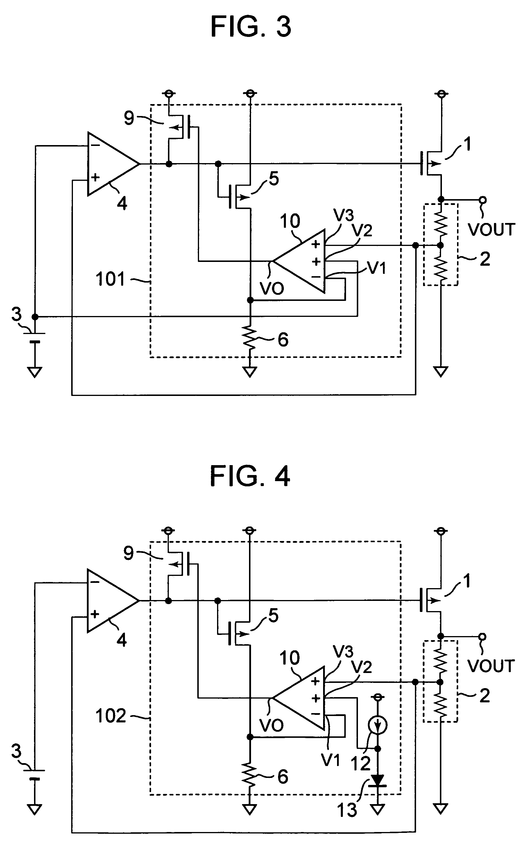
second embodiment

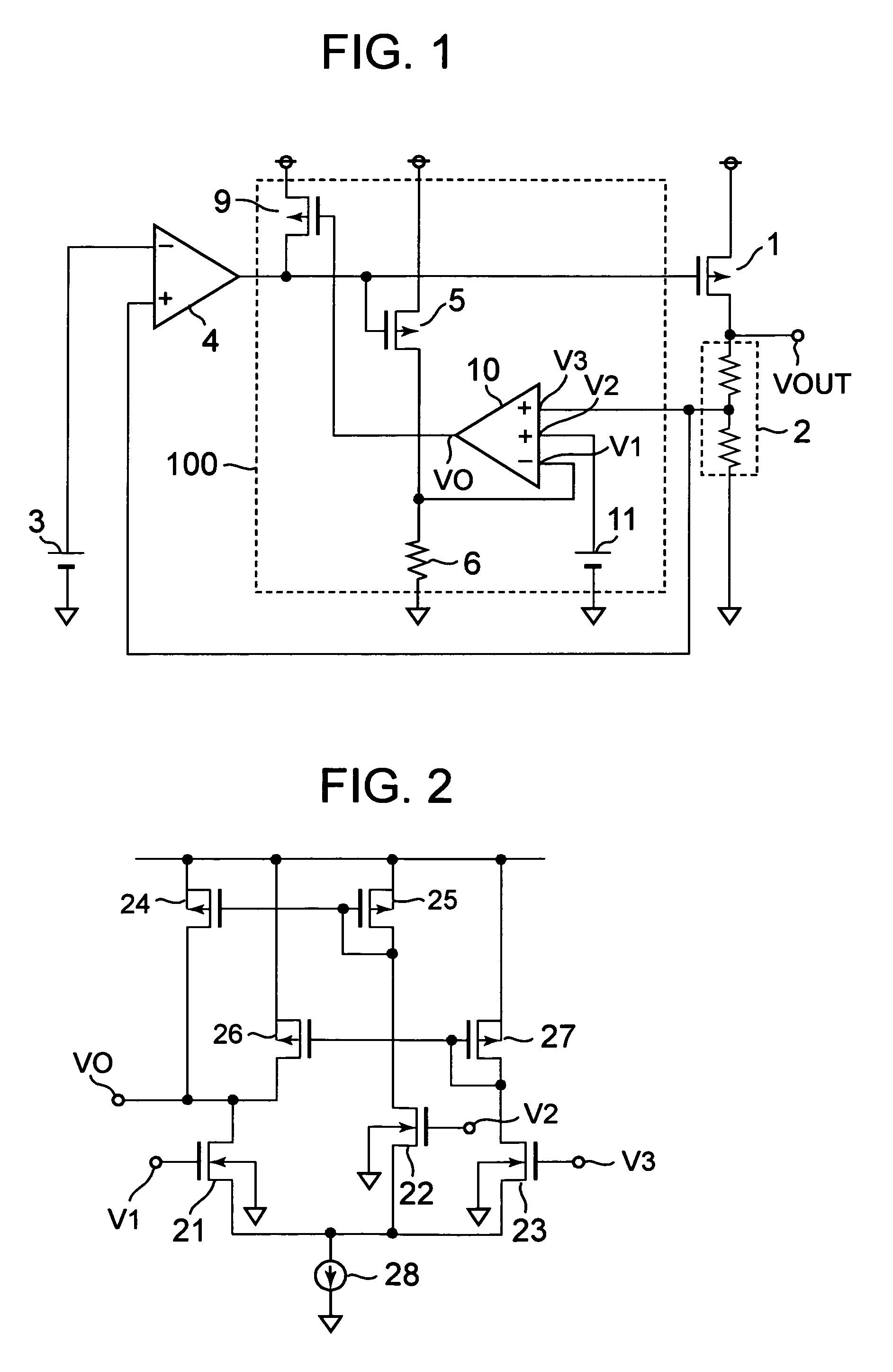
[0036]The second error amplifier 10 of FIG. 2 described above is applicable to a voltage regulator according to the present invention, which is illustrated in FIG. 3 and FIG. 4.

[0037]The overcurrent protection circuit 100 as described above has a function of operating as follows to protect the circuit from the overcurrent.

[0038]In the case where the output current of the output terminal Vout increases, the detection current in accordance with the output current flows through the output current detection transistor 5. When the detection current flows through the detection resistor 6, the voltage of the inverting input terminal V1 of the second error amplifier 10 increases. The second reference voltage Vref2 is input to the first non-inverting input terminal V2 of the second error amplifier 10, and the divided voltage Vdiv is input to the second non-inverting input terminal V3 thereof. In a normal operating state, the divided voltage Vdiv is equal to the second reference voltage Vref2...


PUM


Abstract

A voltage regulator has a first error amplifier circuit that amplifies a difference between a first reference voltage and a voltage based on an output voltage of an output transistor, and an overcurrent protection circuit that detects an overcurrent flowing through the output transistor and limits a current of the output transistor. The overcurrent protection circuit has an output current detection transistor that feeds a detection current in accordance with an output current of the output transistor, a voltage generation circuit that generates a voltage based on the detection current, a second error amplifier circuit that amplifies a difference between the voltage from the voltage generation circuit and a voltage set by a second reference voltage supplied by a temperature detection circuit and a voltage based on the output voltage, and an output current limiting transistor that controls a gate voltage of the output transistor and has a gate that is controlled by an output of the second error amplifier circuit.

Description

BACKGROUND OF THE INVENTION[0001]1. Field of the Invention[0002]The present invention relates to a voltage regulator that outputs a constant voltage, and more particularly, to an overcurrent protection circuit that reduces an output current to protect a circuit when an overcurrent flows into an output terminal.[0003]2. Description of the Related Art[0004]Voltage regulators are employed as voltage supply sources of circuits in various electronic devices. A function of the voltage regulator is to output a constant voltage to an output terminal without being affected by a voltage variation of an input terminal. Moreover, it is important that the voltage regulator has a function of overcurrent protection in which an output current is reduced to protect a circuit when a current that is supplied to a load from the output terminal increases and exceeds a rated current by a predetermined value (for example, refer to JP 02-189608 A).[0005]FIG. 5 illustrates a circuit diagram of a voltage reg...

Claims


Application Information

Patent Timeline
Patent Type & Authority Patents(United States)
IPC IPC(8): G05F1/573
CPCG05F1/573G05F1/56G05F1/569
Inventor IMURA, TAKASHINAKASHIMO, TAKAO
Owner ABLIC INC
Why Eureka
Try Eureka